


recharges your body with static electricity (for example; DO
NOT move or shuffle your feet, DO NOT touch un-
grounded objects, etc.).
4. If you touch ungrounded objects (recharge your body with
static electricity), firmly touch furnace again before touch-
ing control or wires.
5. Use this procedure for installed and uninstalled (un-
grounded) furnaces.
6. Before removing a new control from its container, dis-
charge your body’s electrostatic charge to ground to protect
the control from damage. If the control is to be installed in
a furnace, follow items 1 through 5 before bringing the
control or yourself into contact with the furnace. Put all
used AND new controls into containers before touching
ungrounded objects.
7. An ESD service kit (available from commercial sources)
may also be used to prevent ESD damage.
INTRODUCTION
The 355MAV Multipoise Condensing Gas-Fired Furnaces are
A.G.A./C.G.A. certified for natural and propane gases and for
installation in alcoves, attics, basements, closets, utility rooms,
crawlspaces, and garages. The furnace is factory-shipped for use
with natural gas. An A.G.A./C.G.A. listed gas conversion kit is
required to convert furnace for use with propane gas.
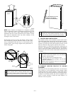
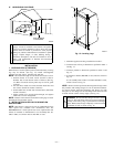
These furnaces SHALL NOT be installed directly on carpeting,
tile, or any other combustible material other than wood flooring. In
downflow installations, accessory floor base MUST be used when
installed on combustible materials and wood flooring. Special base
is not required when this furnace is installed on manufacturer’s
Coil Assembly Part No. CD5 or CK5, or when Coil Box Part No.
KCAKC is used. The design of this furnace line is not
A.G.A./C.G.A. certified for installation in mobile homes, recre-
ation vehicles, or outdoors. These furnaces are suitable for
installation in a residence built on site or a manufactured residence
completed at final site.
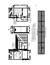
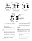
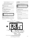
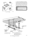
These furnaces are shipped with the drain and pressure tubes
connected for UPFLOW applications. Minor modifications are
required when used in DOWNFLOW, HORIZONTAL RIGHT, or
HORIZONTAL LEFT (supply-air discharge direction) applica-
tions as shown in Fig. 1. See details in Applications section.
These furnaces are shipped with the following materials to assist in
proper furnace installation. These materials are shipped in the main
blower compartment.
Installer Packet includes:
Installation, Start-Up, and Operating Instructions
Service and Maintenance Procedures
User’s Information Manual
Warranty Certificate
Loose Parts Bag includes: Quantity
Pressure tube extension 1
Collector box or condensate trap extension tube 1
Inducer housing drain tube 1
1/2-in. CPVC street elbow 2
Drain tube coupling 1
Drain tube coupling grommet 1
Vent and combustion-air pipe support 2
Combustion-air pipe perforated disk assembly 1
Before installing the furnace in the United States, refer to the
current edition of the NFGC and the NFPA 90B. For further
information, the NFGC and the NFPA 90B are available from
National Fire Protection Association Inc., Batterymarch Park,
Quincy, MA 02269; American Gas Association, 1515 Wilson
Boulevard, Arlington, VA 22209; or from Literature Distribution.
Before installing the furnace in Canada, refer to the current edition
of the NSCNGPIC. Contact Standards Department of Canadian
Gas Association, 55 Scarsdale Road, Don Mills, Ontario, Canada
M3B 2R3.
Installations must comply with regulations of serving gas supplier
and local building, heating, plumbing, or other codes in effect in
area in which installation is made. In absence of local codes,
installation must conform with NFGC.
Canadian installations must be made in accordance with NSCNG-
PIC and all authorities having jurisdiction.
These instructions cover minimum requirements for a safe instal-
lation and conform to existing national standards and safety codes.
In some instances, these instructions exceed certain local codes
and ordinances, especially those that may not have kept pace with
changing residential construction practices. We require these
instructions as a minimum for a safe installation.
CAUTION: Application of this furnace should be in-
doors with special attention given to vent sizing and
material, gas input rate, air temperature rise, unit leveling,
and unit sizing. Improper installation or misapplication of
furnace can require excessive servicing or cause prema-
ture component failure.
WARNING: Improper installation, adjustment, alter-
ation, service, maintenance, or use can cause carbon
monoxide poisoning, explosion, fire, electrical shock, or
other conditions which may cause personal injury or
property damage. Consult a qualified installer, service
agency, local gas supplier, or your distributor or branch
for information or assistance. The qualified installer or
agency must use only factory-authorized and listed kits or
accessories when modifying this product. Failure to
follow this warning could result in electrical shock, fire,
personal injury, or death.
For accessory installation details, refer to applicable installation
literature.
APPLICATIONS
I. GENERAL
Some assembly and modifications are required for furnaces
installed in any of the 4 applications shown in Fig. 1. All drain and
pressure tubes are connected as shown in Fig. 5. See appropriate
application instructions for these procedures.
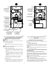
II. UPFLOW APPLICATIONS
An upflow furnace application is where furnace blower is located
below combustion and controls section of furnace, and conditioned
air is discharged upwards.
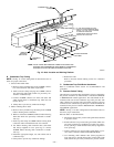
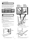
A. Condensate Trap Location (Factory-Shipped
Orientation)
The condensate trap is factory installed in the blower shelf and
factory connected for UPFLOW applications. A factory-supplied
tube is used to extend the condensate trap drain connection to the
desired furnace side for field drain attachment. See Condensate
Trap Tubing (Factory-Shipped Orientation) section for drain tube
extension details.
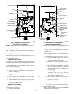
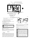
B. Condensate Trap Tubing (Factory-Shipped
Orientation)
NOTE: See Fig. 5 or tube routing label on main furnace door to
confirm location of these tubes.
1. Collector Box Drain, Inducer Housing Drain, Relief Port,
and Pressure Switch Tubes
These tubes should be factory attached to condensate trap
and pressure switch ready for use in UPFLOW applications.
These tubes can be identified by their connection location
—4—
→