


The blower reduces its speed to low-heat RPM. The blower
and EAC remain operating 90, 135, 180, or 225 sec
(depending on blower off time selection). The furnace is
factory set for a 90-sec blower off delay.
10. Post purge—The inducer continues operating for 15 sec
after gas valve is de-energized.
III. HEATING MODE—TWO STAGE
The control center provides 2-stage heating using a single-stage
thermostat. The control center maximizes comfort while optimiz-
ing efficiency to meet the demands of conditioned area when a
thermostat R-W/W1 signal is received.
If thermostat control over furnace staging is desired, a 2-stage
thermostat can be used. When control center receives a thermostat
R-W/W1 and R-W2 signal, high heat is energized and when a
R-W/W1 signal alone is received, low heat is energized. This
method overrides microprocessor control of high or low heat.
NOTE: When using 2-stage thermostat operation with R-W/W1
and R-W2 signals, setup switch SW-2 MUST be in ON position.
The heat cycle operates as stated in Heating Mode section.
To allow for greater comfort, 2-stage thermostat control is recom-
mended when zone systems are used.
IV. EMERGENCY HEAT MODE
NOTE: The furnace should not be operated in emergency heat
mode for extended periods of time. Operation is only recom-
mended to provide heat until replacement components can be
obtained or fault resolved.
In this mode, the microprocessor is bypassed and motors operate at
full speed with high-heat operation. The heat exchangers, motors,
and electronics can be overstressed and may reduce the life of
components if operated for an extended period.
NOTE: No safeties are bypassed when using emergency heat
mode.
Emergency heat mode can be selected using setup switch SW-4.
SW-4 should be used when a fault condition exists or difficult to
resolve problems occur. This allows heating until fault can be
corrected.
In emergency heat mode, the normal heat mode outlined in
Heating Mode section is not followed. The following sequence
will occur:
When thermostat calls for heat, the R-W/W-1 circuits close.
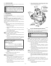
1. Prepurge period—The inducer motor is turned on IMME-
DIATELY operating at maximum speed, closing low- and
high-pressure switches. Prepurge begins 25 sec after high-
pressure switch closes.
2. Blower on—The blower motor is turned on IMMEDI-
ATELY and slowly increases to maximum speed as soon as
a call for heat is received. No blower calibration occurs.
3. Electronic Air Cleaner—The EAC-1 terminal does not
operate in emergency heat mode.
4. Humidifier—The HUM terminal is energized IMMEDI-
ATELY.
5. Ignitor warm up—The HSI is energized for a 17 sec
warm-up period after prepurge period is completed.
6. Ignition sequence—After HSI warm-up period has com-
pleted, the gas valve is energized, permitting gas flow to
burners where it is ignited. After 5 sec, the HSI is
de-energized, and a 2-sec flame-sensing period begins.
NOTE: Emergency heat mode only operates in high heat.
7. Flame sensing—When burner flame is sensed, control
center holds gas valve open. If burner flame is not sensed,
control center de-energizes gas valve and ignition sequence
is repeated.
NOTE: Ignition sequence repeats 3 additional times before lock-
out occurs. Lockout automatically resets after 3 hr, or can be
manually reset by turning 115-v or 24-v power off (not at
thermostat) for 3 sec minimum, then turning on again. Fault codes
will not flash in emergency heat mode.
8. Blower off delay—When thermostat is satisfied, the
R-W/W1 signal is terminated, de-energizing gas valve
(stopping gas flow to burners), and HUM terminal is
de-energized. The blower stops immediately.
9. Post purge—Post purge does NOT occur. The inducer
stops immediately.
V. COOLING MODE
A. Single-Speed Applications
When thermostat calls for cooling, the R-G and R-Y/Y2 circuits
close.
1. Cooling unit—The cooling unit starts when thermostat
R-Y signal is received.
2. Blower on—The control center starts blower immediately
when it receives an R-Y/Y2 and R-G signal. The blower
starts at approximately 400-500 RPM. After 20 sec, the
blower is turned off for 1/10 of a sec where a coast down
calibration is done to evaluate resistance of the conditioned
air duct system. The microprocessor then determines
blower RPM required to provide selected cooling airflow.
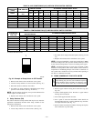
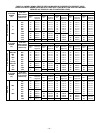
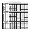
NOTE: In cooling mode, the microprocessor adjusts blower RPM
to operate at 400 CFM per ton as selected on A/C setup switches.
See Air Conditioning Setup Switches section. There is also a chart
on wiring diagram. (See Fig. 24.)
NOTE: If Y/Y2 thermostat lead is not connected to furnace
control center, blower motor operates in continuous fan speed and
indoor coil freeze-up may occur.
3. Electronic Air Cleaner—The EAC-1 terminal is energized
whenever blower operates.
4. Cooling unit—The cooling unit stops when thermostat R-Y
signal is terminated.
5. Blower off delay—When thermostat is satisfied, the
R-Y/Y2 and R-G signals are terminated, and blower re-
mains operating for 90 sec.
B. Two-Speed Applications
For details on 2-speed cooling applications, refer to Fig. 43.
VI. HEAT PUMP MODE
A. Single-Speed Applications
When furnace is operating in heat pump heating mode, R-Y/Y2
and R-G circuits are closed energizing heat pump, and blower
operates at cooling speed. When heat pump defrost is required,
R-W/W1 circuits close starting gas heat cycle, and blower adjusts
to low-heat speed.
1. Prepurge period—The inducer motor is turned on and
slowly comes up to speed. When low-pressure switch
closes, inducer motor RPM is noted by microprocessor, and
a 25 sec prepurge period begins. The RPM is used to
evaluate vent system resistance. This evaluation is then
used to determine required RPM necessary to operate
inducer in low-heat mode.
NOTE: The heat cycle can start in either high or low heat. If a
high-heat cycle is initiated, inducer continues increasing its speed
after low-pressure switch closes. When high-pressure switch
closes, inducer motor RPM is noted by microprocessor before the
25 sec prepurge period begins. The RPM is used to evaluate vent
system resistance. This evaluation is used to determine required
RPM necessary to operate inducer in high-heat mode.
—32—