


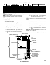
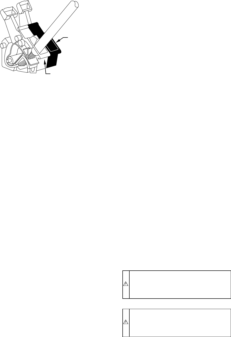
(5.) Insert EAC stripped leads into control center EAC
terminals by depressing terminal’s arm with a
screwdriver or finger. (See Fig. 26.)
(6.) Reinstall control box to furnace blower shelf using
2 screws removed earlier.
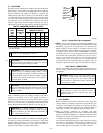
2. Humidifier (HUM)
Screw terminals (HUM and C
OM) are provided for 24-v
humidifier connection. (See Fig. 24.) HUM terminal is
energized with 24v (0.5-amp maximum) after inducer
motor prepurge period.
NOTE: A field-supplied, 115-v controlled relay connected to
EAC terminals may be added if humidifier operation is desired
during blower operation.
3. Dehumidification (DH)
A 1/4-in. male quick-connect terminal is provided on
control center to attach a normally open (N/O) humidistat
contact when dehumidification is desired. (See Fig. 25.)
Connect humidistat to thermostat R terminal and DH
terminal on control center. A 15 percent reduction of
cooling airflow or constant fan airflow will occur when DH
terminal is energized and a single- or 2-speed "call for
cooling" is received.
DIRECT VENTING
The 355MAV Furnaces require a dedicated (one 355MAV furnace
only) direct-vent system. In a direct-vent system, all air for
combustion is taken directly from outside atmosphere, and all flue
products are discharged to outside atmosphere.
I. REMOVAL OF EXISTING FURNACES FROM
COMMON VENT SYSTEMS
If furnace being replaced was connected to a common vent system
with other appliances, the following steps shall be followed with
each appliance connected to the venting system placed in opera-
tion, while any other appliances connected to the venting system
are not in operation:
1. Seal any unused openings in the venting system.
2. Inspect the venting system for proper size and horizontal
pitch as required in the National Fuel Gas Code, ANSI
Z223.1 or the CAN/CGA B149 Installation Codes and these
instructions. Determine that there is no blockage or restric-
tion, leakage, corrosion, and other deficiencies which could
cause an unsafe condition.
3. If practical, close all building doors and windows and all
doors between the space in which the appliance(s) con-
nected to the venting system are located and other spaces of
the building. Turn on clothes dryers and any appliance not
connected to the venting system. Turn on any exhaust fans,
such as range hoods and bathroom exhausts, so they shall
operate at maximum speed. Do not operate a summer
exhaust fan. Close fireplace dampers.
4. Follow the lighting instructions. Place the appliance being
inspected in operation. Adjust thermostat so appliance shall
operate continuously.
5. Test for draft hood equipped appliance spillage at the draft
hood relief opening after 5 minutes of main burner opera-
tion. Use the flame of a match or candle.
6. After it has been determined that each appliance connected
to the venting system properly vents when tested as outlined
above, return doors, windows, exhaust fans, fireplace damp-
ers, and any other gas-burning appliance to their previous
conditions of use.
7. If improper venting is observed during any of above tests,
the venting system must be corrected.
Vent system or vent connectors may need to be resized. For any
other appliances when resizing vent systems or vent connectors,
system or connector must be sized to approach minimum size as
determined using appropriate table found in the NFGC or NSC-
NGPIC.
II. COMBUSTION-AIR AND VENT PIPING
A. General
Combustion-air and vent pipe fittings must conform to American
National Standards Institute (ANSI) standards and American
Society for Testing and Materials (ASTM) standards D1785
(schedule-40 PVC), D2665 (PVC-DWV), D2241 (SDR-21 and
SDR-26 PVC), D2661 (ABS-DWV), F628 (schedule-40 ABS), or
F891 (PVC-DWV cellular core). Pipe cement and primer must
conform to ASTM standards D2564 (PVC) or D2235 (ABS). See
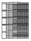
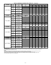
Table 6 for maximum pipe lengths and Fig. 31, 32, 33, 34, and 35
for exterior piping arrangements.
In Canada, construct all combustion-air and vent pipes for this unit
of CSA or ULC certified schedule-40 PVC, PVC-DWV or
ABS-DWV pipe and pipe cement. SDR pipe is NOT approved in
Canada.
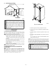
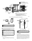
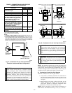
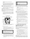
NOTE: Furnace combustion-air and vent pipe connections are
sized for 2-in. pipe. Any pipe size change should be made outside
furnace casing in vertical pipe. (See Fig. 27.) This allows proper
drainage of vent condensate.
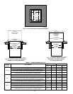
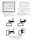
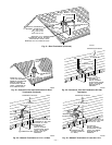
Combustion-air and vent pipes must terminate together in same
atmosphere pressure zone, either through roof or sidewall (roof
termination preferred), using accessory termination kit. See Table
5 for required clearances.
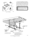
Furnace combustion-air and vent pipe connections must be at-
tached as shown in Fig. 28. Combustion-air intake plug fitting and
inducer housing alternate vent cap may need to be relocated in
some applications.
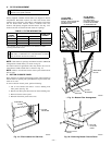
CAUTION: When combustion-air pipe is installed
above a suspended ceiling, pipe must be insulated with
3/8-in. thick Armaflex-type insulation. Combustion-air
pipe should also be insulated when it passes through a
warm, humid space.
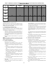
CAUTION: When vent pipe is exposed to temperatures
below freezing, such as when it passes through an
unheated space or when a chimney is used as a raceway,
pipe must be insulated as shown in Table 7 with
Armaflex-type insulation.
Fig. 26—EAC Terminals on Control Center
A93053
EAC2
EAC1
—21—