


VI. GAS PIPING
Gas piping must be installed in accordance with national and local
codes. Refer to current edition of NFGC. Canadian installations
must be made in accordance with NSCNGPIC and all authorities
having jurisdiction. Gas supply line should be a separate line
running directly from meter to furnace, if possible. Refer to Table
3 for recommended gas pipe sizing. Risers must be used to connect
to furnace and to meter. Support all gas piping with appropriate
straps, hangers, etc. Use a minimum of 1 hanger every 6 ft. Joint
compound (pipe dope) should be applied sparingly and only to
male threads of joints. Pipe dope must be resistant to propane gas.
CAUTION: Connect gas pipe to furnace using a backup
wrench to avoid damaging gas controls.
WARNING: Gas valve shutoff switch MUST be facing
forward or tilted upward. Failure to follow this warning
could result in property damage or death.
WARNING: Never purge a gas line into a combustion
chamber. Never use matches, candles, flame, or other
sources of ignition for purpose of checking leakage. Use
a soap-and-water solution to check for leakage. A failure
to follow this warning could result in fire, explosion,
personal injury, or death.
WARNING: Use proper length of pipe to avoid stress on
gas control manifold. Failure to follow this warning could
result in a gas leak resulting in fire, explosion, personal
injury, or death.
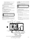
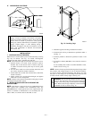
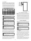
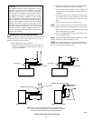
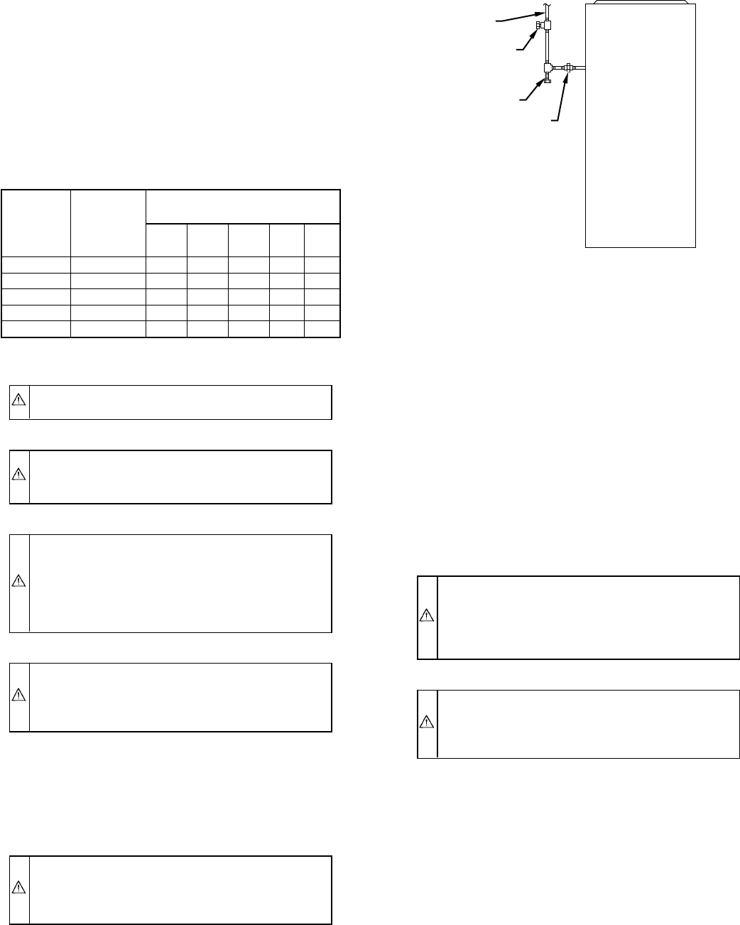
Install a sediment trap in riser leading to furnace. Trap can be
installed by connecting a tee to riser leading to furnace so
straight-through section of tee is vertical. Then connect a capped
nipple into lower end of tee. Capped nipple should extend below
level of gas controls. Place a ground joint union between gas
control manifold and manual gas shutoff valve. (See Fig. 21.)
CAUTION: If a flexible connector is required or al-
lowed by authority having jurisdiction, black iron pipe
shall be installed at gas valve and extend a minimum of
2 in. outside furnace casing.
An accessible manual shutoff valve MUST be installed upstream
of furnace gas controls and within 6 ft of furnace. A 1/8-in. NPT
plugged tapping, accessible for test gage connection, MUST be
installed immediately upstream of gas supply connection to
furnace and downstream of manual shutoff valve.
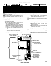
NOTE: The gas valve inlet press tap connection is suitable to use
as test gage connection providing test pressure DOES NOT exceed
maximum 0.5 psig (14-in. wc) stated on gas valve. (See Fig. 48.)
Piping should be pressure tested in accordance with local and
national plumbing and gas codes before furnace has been attached.
In Canada, refer to current edition of NSCNGPIC. If pressure
exceeds 0.5 psig (14-in. wc), gas supply pipe must be disconnected
from furnace and capped before pressure test. If test pressure is
equal to or less than 0.5 psig (14-in. wc), turn off electric shutoff
switch located on gas valve before test. It is recommended that
ground joint union be loosened before pressure testing. After all
connections have been made, purge lines and check for leakage.
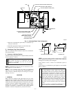
ELECTRICAL CONNECTIONS
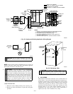
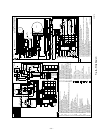
See Fig. 22 for field wiring diagram showing typical field 115-v
and 24-v wiring. Check all factory and field electrical connections
for tightness.
WARNING: Blower access panel door switch opens
115-v power to control center. No component operation
can occur. Do not bypass or close switch with panel
removed. Failure to follow this warning could result in
personal injury or death.
CAUTION: Furnace control must be grounded for
proper operation or control will lock out. Control is
grounded through green wire routed to gas valve and
burner box screw.
I. 115-V WIRING
Before proceeding with electrical connections, make certain that
voltage, frequency, and phase correspond to that specified on unit
rating plate. Also, check to be sure that service provided by utility
is sufficient to handle load imposed by this equipment. Refer to
rating plate or Table 4 for equipment electrical specifications.
Make all electrical connections in accordance with NEC
ANSI/NFPA 70-1996 and any local codes or ordinances that might
apply. For Canadian installations, all electrical connections must
be made in accordance with Canadian Electrical Code CSA C22.1
or subauthorities having jurisdiction.
Use a separate, fused branch electrical circuit containing a properly
sized fuse or circuit breaker for this furnace. See Table 4 for wire
size and fuse specifications. A disconnecting means must be
located within sight from and readily accessible to furnace.
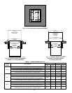
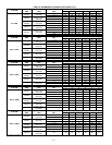
TABLE 3—MAXIMUM CAPACITY OF PIPE*
NOMINAL
IRON
PIPE
SIZE
(IN.)
INTERNAL
DIAMETER
(IN.)
LENGTH OF PIPE (FT)
10 20 30 40 50
1/2 0.622 175 120 97 82 73
3/4 0.824 360 250 200 170 151
1 1.049 680 465 375 320 285
1-1/4 1.380 1400 950 770 660 580
1-1/2 1.610 2100 1460 1180 990 900
* Cubic ft of gas per hr for gas pressures of 0.5 psig (14-in. wc) or less, and a
pressure drop of 0.5-in. wc (based on a 0.60 specific gravity gas). Ref: Table
10-2 NFPA 54-1996.
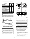
Fig. 21—Typical Gas Pipe Arrangement
A93324
UNION
SEDIMENT
TRAP
MANUAL
SHUTOFF
VALVE
(REQUIRED)
GAS
SUPPLY
—17—
→
→
→