


CAUTION: Combustion air must not be taken from
inside structure because that air is frequently contami-
nated by halogens, which include fluorides, chlorides,
bromides, and iodides. These elements are found in
aerosols, detergents, bleaches, cleaning solvents, salts, air
fresheners, adhesives, paint, and other household prod-
ucts. Locate combustion-air inlet as far as possible from
swimming pool and swimming pool pump house.
Excessive exposure to contaminated combustion air will
result in safety and performance related problems.
WARNING: Solvent cements are combustible. Keep
away from heat, sparks, and open flame. Use only in well
ventilated areas. Avoid breathing in vapor or allowing
contact with skin or eyes. Failure to follow this warning
could result in fire, property damage, personal injury, or
death.
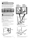
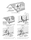
WARNING: All combustion-air and vent pipes must be
airtight and watertight. Pipes must also terminate exactly
as shown in Fig. 31, 32, 33, 34, or 35. Failure to follow
this warning could result in property damage, personal
injury, or death.
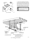
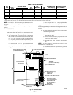
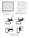
NOTE: The minimum combustion-air and vent pipe length (each)
for these furnaces is 5 ft. Short pipe lengths (5-8 ft) may discharge
water droplets. These droplets may be undesirable, and a 12-in.
minimum offset pipe section is recommended, as shown in Fig. 29,
to reduce excessive droplets from exiting vent pipe outlet.
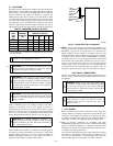
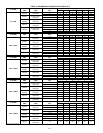
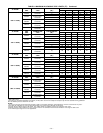
B. Combustion-Air and Vent Pipe Diameter
Determine combustion-air and vent pipe diameter.
1. Using Table 6, individually determine the combustion-air
and vent pipe diameters. Pick the larger of these 2 pipe
diameters and use this diameter for both combustion-air and
vent pipes.
2. When installing vent systems of short pipe length, use the
smallest allowable pipe diameter. Do not use pipe size
greater than required or incomplete combustion, flame
disturbance, or flame sense lockout may occur.
NOTE: Do not count elbows or pipe sections in terminations or
within furnace. See shaded areas in Fig. 31, 32, 33, 34, and 35.
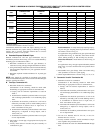
TABLE 5—COMBUSTION-AIR AND VENT PIPE
TERMINATION CLEARANCES
LOCATION
CLEARANCE (FT)
U.S.A. Canada
Above grade level or above antici-
pated snow depth
11†
Dryer vent 33
From plumbing vent stack 33
From any mechanical fresh air intake 16
For furnaces with an input capacity
less than 100,000 Btuh—from any
non-mechanical air supply (windows
or doors which can be opened) or
combustion-air opening
11
For furnaces with an input capacity
greater than 100,000 Btuh—from any
non-mechanical air supply (windows
or doors which can be opened) or
combustion-air opening
13
From service regulator vent, electric
and gas meters, and relief equipment
4* 6‡
Above grade when adjacent to public
walkway
77
* Horizontal distance.
† 18 in. above roof surface in Canada.
‡ 36 in. to electric meter in Canada only.
NOTES:
1. If installing 2 adjacent 355MAV Furnaces, refer to Multiventing and Vent
Terminations section for proper vent configurations.
2. Whenlocating combustion-air and vent terminations, consideration must be
given to prevailing winds, location, and other conditions which may cause
recirculation of the appliance’s own flue products or the flue products of
adjacent vents. Recirculation can cause poor combustion, inlet condensate
problems, and accelerated corrosion of heat exchangers.
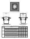
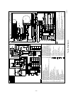
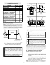
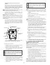
Fig. 27—Combustion-Air and Vent Pipe Diameter
Transition Location and Elbow Configuration
A93034
FURNACE
PIPE DIAMETER
TRANSITION IN
VERTICAL SECTION
NOT IN
HORIZONTAL
SECTION
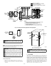
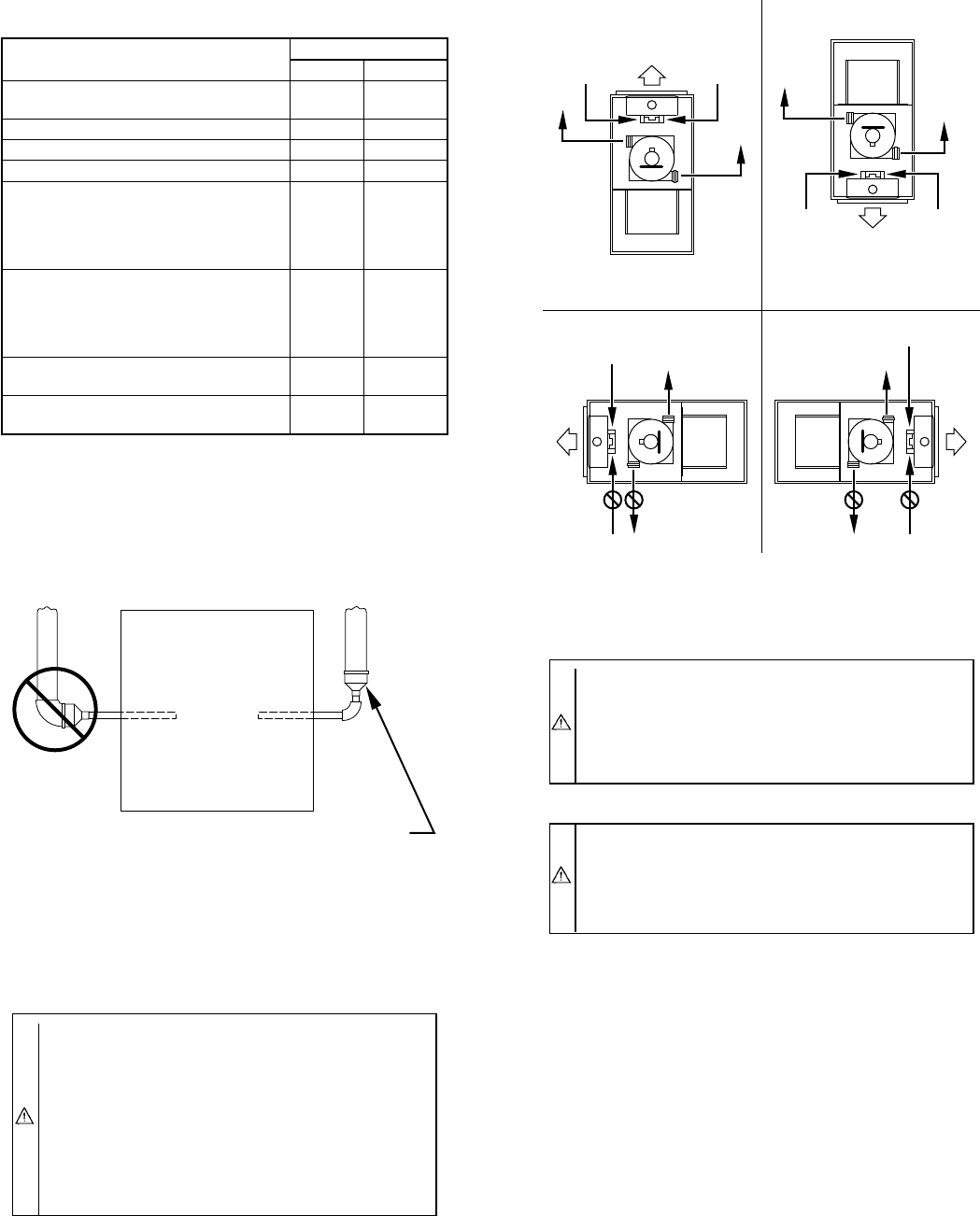
Fig. 28—Combustion-Air and Vent Pipe Connections
A96187
COMBUSTION-
AIR
COMBUSTION-
AIR
AIR
FLOW
VENT
VENT
VENT
AIR
FLOW
AIR
FLOW
AIR
FLOW
UPFLOW DOWNFLOW
HORIZONTAL-LEFT DISCHARGE HORIZONTAL-RIGHT DISCHARGE
Select 1 vent pipe connection and
1 combustion-air pipe connection.
COMBUSTION-
AIR
COMBUSTION-
AIR
COMBUSTION-
AIR
COMBUSTION-
AIR
VENT
VENT
VENT
NOTE: Select 1 vent pipe connection and
1 combustion-air pipe connection.
NOTE:
—22—