


2. Humidifier—The HUM terminal is energized after inducer
prepurge period is completed.
3. Ignitor warm up—After prepurge period, HSI is energized
for 17 sec.
4. Ignition sequence—After HSI warm-up period is com-
pleted, the gas valve is energized, permitting gas flow to the
burners where it is ignited. After 5 sec, the HSI is
de-energized, and a 2-sec flame-sensing period begins.
5. Flame sensing—When burner flame is sensed, control
center holds gas valve open.
If burner flame is not sensed, control center de-energizes
gas valve, and ignition sequence is repeated.
6. Blower off period—Ten sec after gas valve is energized,
the blower stops for 25 sec to allow heat exchangers to
warm up.
7. Blower on delay—After blower off period, blower starts.
NOTE: The blower starts at approximately 400-500 RPM. After
20 sec, the motor is turned off for 1/10 of a sec where a coast down
calibration is done to evaluate resistance of the conditioned air
duct system. The microprocessor then determines blower RPM
required to provide proper airflow for heating mode.
8. Electronic Air Cleaner—The EAC-1 terminal is energized
whenever blower operates.
9. Inducer speed operation—If cycle starts in low heat,
inducer speed reduces slightly after the flame sense. If cycle
starts in high heat, inducer speed increases 15 sec after
flame sense. The reduction in speed in low heat is to
optimize combustion for maximum efficiency.
10. Call for heat terminated—When the call for heat is
satisfied, the R-W/W1 signal is terminated, de-energizing
gas valve (stopping gas flow to burners), and HUM terminal
is de-energized.
a. R-W/W1 signal terminated with R-Y/Y2 and R-G
still present—The blower changes its speed to cooling
RPM.
b. R-W/W1 with R-Y/Y2 and R-G signals terminated—
The blower continues to operate completing a normal
blower off delay.
11. Post purge—The inducer continues operating for 15 sec
after gas valve is de-energized.
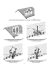
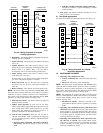
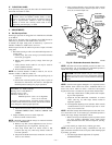
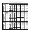
B. Two-Speed Applications
For details on 2-speed heat pump applications, refer to Fig. 44.
VII. CONTINUOUS FAN MODE
1. Operating with continuous fan only—
a. Call for continuous fan—The thermostat closes R-G
circuit.
b. Blower on—The blower starts immediately.
NOTE: The blower starts at approximately 400-500 RPM. After
20 sec, the motor is turned off for 1/10 of a sec where a coast down
calibration is done to evaluate resistance of the conditioned air
duct system. The microprocessor then determines blower RPM
required to provide proper airflow for heating mode.
NOTE: The continuous fan speed is the same as low-heat speed
unless it is field adjusted to another desired airflow. See Continu-
ous Fan Setup Switches section. There is also a chart on wiring
diagram. (See Fig. 24.)
c. Electronic Air Cleaner—The EAC-1 terminal is ener-
gized whenever blower operates, regardless of operating
mode.
2. Operating with continuous fan (R-G) and call for heat
(R-W/W1) is received—Same as heat pump mode except
blower on delay is 10 sec less than heat mode. After call for
heat (R-W/W1) is terminated, the blower remains operating
at low-heat speed for selected blower off delay before
resuming continuous fan speed.
3. Operating with continuous fan (R-G) and call for cool-
ing (R-Y/Y2) is received—See Cooling Mode section.
After call for cooling (R-Y/Y2) is terminated, the blower
remains operating at cooling speed for 90 sec before
resuming continuous fan speed.
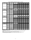
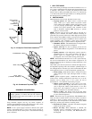
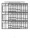
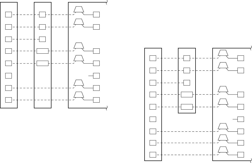
Fig. 43—Wiring Schematic for 2-Speed
Cooling Applications
A94302
R R
C C
Y2 Y2
E
W2
G
L L
Y1 Y1
VARIABLE
SPEED
THERMOSTAT
2-SPEED
THERMOSTAT
2-SPEED AIR
CONDITIONER
W3
W2
R
C
Y/Y2
W/W1
G
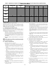
Fig. 44—Wiring Schematic for 2-Speed
Heat Pump Applications
A94303
R R
C C
Y2 Y2
E
W2
G
O O
L L
Y1 Y1
VARIABLE
SPEED
THERMOSTAT
2-SPEED
THERMOSTAT
2-SPEED
HEAT PUMP
W3
W2
R
C
Y/Y2
W/W1
G
—33—