


28
LK3-B448E MARK2/BA-16
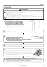
6. Checking the sewing pattern
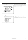
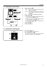
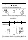
7. Depress the foot switch to the second step.
Only the feed mechanism will move.
The feed mechanism moves forward by one stitch each time the foot switch is depressed.
Each time the feed mechanism is moved forward by one stitch, turn the machine pulley by hand
and check that the needle goes into the holes in the button without touching the button. Do this
for each hole position. (NOTE)
After checking is complete, depress the foot switch to move the feed mechanism to the end
position.
* If you depress the foot switch to the 2nd step and keep it depressed until after the feed mechanism has
started to move, the feeding speed will increase.
* If you would like to stop the feed while it is moving, press the TEST switch.
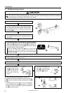
6. If the setting was not changed in step 4, proceed to step 7.
Depress the foot switch to the second step.
(Home position detection will be carried out. The work clamp will not rise because this is test mode.)
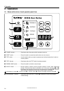
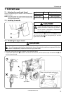
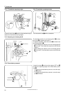
1. Turn on the power switch.
(The POWER indicator will illuminate and the program number will flash in the display window.)
5. Press the TEST switch.
(The TEST indicator will illuminate.)
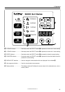
8. Press the TEST switch.
(The TEST indicator will switch off and the test mode will be cleared.)
9. Depress the foot switch.
The work clamp will rise and the preparation for sewing will be completed.
TEST
TEST
1st step
2nd step
6. Checking the sewing pattern
■ When checking by operating only the feed mechanism
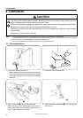
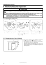
To ensure safety during use ......
You can prevent accidental changes being made to
programs by setting DIP switches 7 and 8 to ON.
When DIP switch 7 is ON
... The sewing pattern cannot be enlarged.
When DIP switch 8 is ON
... The program number cannot be changed.
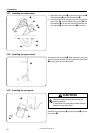
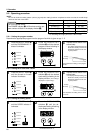
3. Set the button. (Press the MANUAL switch on the button feeder.)
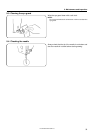
NOTE: If the needle touches the button, carry out the following.
1.Check that the needle size correctly matches the diameter of the holes in the button. (Refer to “7-1. Selecting the
needle and thread”.)
2.Make fine adjustments to the X-scale and Y-scale. (Refer to “5-2-2. Setting the X-scale and Y-scale”.)
3.Adjust the position of the button holder. (Refer to “10-10. Adjusting the position of the button holder”.)
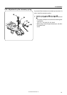
2. Depress the foot switch to the second step.
(After the home position is detected, the button clamp will rise.)
4. Set the X-scale and Y-scale in accordance with the hole pitch of the buttons being used.
(Refer to “5-2-2. Setting the X-scale and Y-scale”.)
()