


14
3. Installation
LK3-B448E MARKII/BA-16
3-14. Connecting the cords
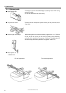
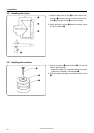
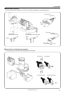
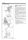
1. Gently tilt back the machine head.
NOTE:
After tilting back the machine head, do not push the face side or the pulley side from above.
2. Pass the cords q through the hole w in the work table.
3. Gently return the machine head to its original position.
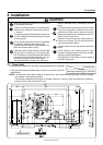
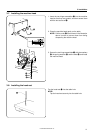
4. Remove the six screws e, and then open the control box cover (main P.C. board mounting plate r).
NOTE:
When opening the cover, hold it securely so that it does not fall down.
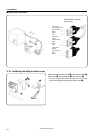
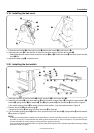
5. Loosen the two screws t, and then open the cord presser plate y in the direction of the white arrow and pass
the cords q through the opening.
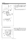
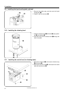
6. Loosen the screw o, and then attach the ground cord u for the machine head and the ground cord i for the
operation panel as shown in the illustration.
7. Loosen the screw !1, and then attach the ground cord !0 for the upper shaft motor as shown in the illustration.
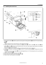
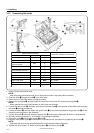
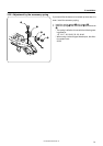
8. Securely connect connectors P1 to P8 and P11 as indicated in the table.
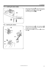
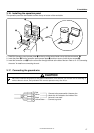
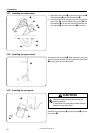
9. Secure the cords q with the cord clamps !2 and !3.
10.Close the cord presser plate y in the direction of the black arrow, and secure it by tightening the screws t.
NOTE:
Check that the cords do not get pulled when the machine head is tilted back gently.
11.Tighten the cover (main P.C. board mounting plate r) with the six screws e.
P8
P1
P2
P3
P4
P5
P6
P7
P11
Connection location
X, Y, Sewing sensor
Synchronizer
Machine specification
select connector
Thread take-up solenoid
Presser solenoid
Thread trimmer solenoid
Pulse motor, Y
Pulse motor, X
Operation panel
Upper shaft motor
No. of pins
12-pin
5-pin
8-pin
5-pin
4-pin
4-pin (blue)
4-pin
26-pin
1-pin
3-pin
Cord mark
z
x
c
v
b
n
m
None
None
Connection location on circuit board
P1 (ORG2)
P2 (SYNCHRO)
P3 (SELECT)
P4 (SOL2)
P5 (SOL)
P6 (YPM)
P7 (XPM)
P8 (PANEL)
P11 (UVW)
P14
Machine head connectors
BA16
None
NoneBA16 None
BA16 16-pin
None
None P15