


9
THERMAL BALANCER
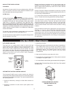
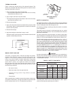
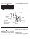
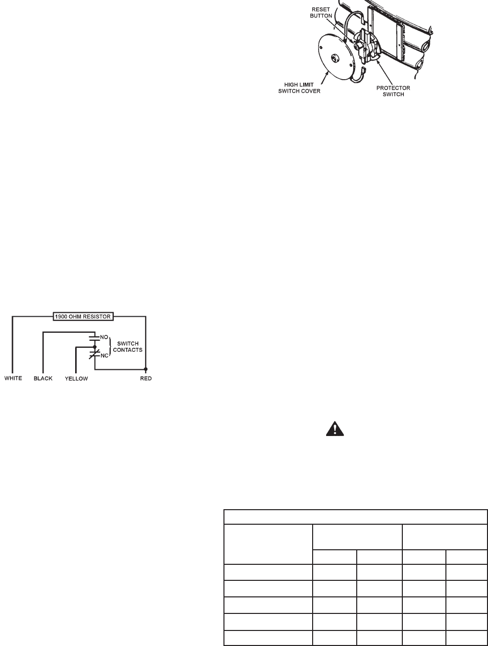
Figure 4 shows the internal wiring of the thermal balancer. The
device may be tested after disconnecting the four leads from their
respective terminals on the unit.
1. Apply a test light to the yellow and red leads.
• The lamp should light as the contact in this circuit is normally
closed when the resistor is cool.
2. Apply a light to the black and yellow leads.
• The lamp should not light as the contact in this circuit is normally
open when the resistor is cool.
3. Remove the test light.
4. Apply 120 volts to the white and red leads which power the 1900
ohm resistor. After a warming period the contacts of the thermal
balancer should operate.
5. Remove the test light.
6. Apply the test light as described in steps 1 and 2.
While the resistor is still warm the lamp indications should be the
opposite as described previously.
FIGURE 4.
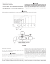
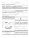
MANUAL RESET HIGH LIMIT
This boiler is equipped with a manual reset high limit switch,
located under the small cover on the side of the jacket, see
Figure 5. This device provides positive shutdown of the
boiler in the event of boiler or system malfunction. Should the
surface temperature of the copper tubing heat exchanger
reach 250°F (120°C), the high limit switch will activate,
the gas valve will close, the pilot and main burners will be
extinguished. If the high limit switch should shut off unit, check
the following conditions:
• No water in boiler.
• Restricted water flow through the boiler.
• Improper wiring (boiler firing without circulator
operating).
• Pump failure.
After correcting failure condition remove the protector switch cover
and push the reset button. The high limit switch may be reset after
the coil surface cools to 6°F (3.3°C) below the trip setting.
HIGH LIMIT SWITCH
FIGURE 5.
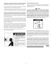
SAFETY FLOW SWITCH
The safety ow switch is a safety device which must be installed at
the water outlet of the unit to prevent main burner operation in the
event of inadequate water ow through the unit.
An accessory package containing a safety ow switch is available
for this application.
This switch may be mounted in a horizontal pipe line or a vertical
pipe line with upward water ow. Do not install the switch where the
water ow is downward.
For proper performance mount the switch in a section of pipe where
there is a straight run of at least 5 pipe diameters on each side of the ow
switch (i.e. do not locate adjacent to valves, elbows, orices, etc.).
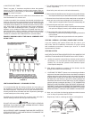
The ow switch shall be mounted in a standard 1-1/2" x 1-1/2" x 1"
tee for a 1-1/2" pipe application. For larger pipe sizes use a reducing
tee in order to keep the switch as close to the pipe as possible. Install
the ow switch in the branch (top) opening of the reducing tee and
provide adequate paddle length in the ow stream. For example in
a 2" pipe installation use a 2" x 2" x 1" reducing tee. For 2", or 3"
pipe use paddle segments as supplied. For other pipe sizes (i.e.
1-1/4", 1-1/2" and 2-1/2") trim the paddle to the proper pipe size, see
Figure 6 on page 10. If a standard tee is used, install a face or hex
bushing in the top opening. The paddle must be adjusted or trimmed
to the size of the pipe in which it will be installed.
CAUTION
Any part of the paddle must not touch the pipe or any restrictions in
the pipe. Screw the ow switch in position so the at of the paddle
is at right angles to the ow. The arrow on the side case must point
in the direction of the ow.
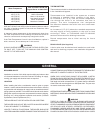
TABLE 3 - SAFETY FLOW SWITCH
Minimum Pipe Rate
Model Number
Contacts Closed
(Flow)
Contacts Open
(No Flow)
GPM LPM GPM LPM
HW-300 5.8 22.0 3.7 14.0
HW-399 7.5 28.4 5.0 18.9
HW-420 7.5 28.4 5.0 18.9
HW-520 13.7 51.9 9.5 36.0
HW-610/670 13.7 51.9 9.5 36.0
The safety ow switch may be eld adjusted to obtain higher
minimum ow rates than those shown in table 3.