


45
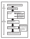
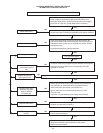
At the time of removal of an existing boiler, the following steps
shall be followed with each appliance remaining connected to
the common venting system placed in operation, while the other
appliances remaining connected to the common venting system
are not in operation.
Seal any unused openings in the common venting system.
Visually inspect the venting system for proper size and horizontal
pitch and determine there is no blockage or restriction, leakage,
corrosion and other deciencies which could cause an unsafe
condition.
Insofar as is practical, close all building doors and windows and
all doors between the space in which the appliances remaining
connected to the common venting system are located and other
spaces of the building. Turn on clothes dryers and any appliance
not connected to the common venting system. Turn on any exhaust
fans, such as range hoods and bathroom exhausts, so they will
operate at maximum speed. Do not operate a summer exhaust fan.
Close replace dampers.
Place in operation the appliance being inspected. Follow the
lighting instructions. Adjust thermostat so appliance will operate
continuously.
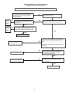
Test for spillage at the draft hood relief opening after 5 minutes of
main burner operation. Use the ame of a match or candle, or smoke
from a cigarette, cigar or pipe.
After it has been determined that each appliance remaining
connected to the common venting system properly vents when tested
as outlined above, return doors, windows, exhaust fans, replace
dampers and any other gas-burning appliance to their previous
condition of use.
Any improper operation of the common venting system should be
corrected so the installation conforms with the National Fuel Gas Code,
ANSI Z223.1 and/or CAN/CSA B149, Installation Codes. When resizing
any portion of the common venting system, the common venting system
should be resized to approach the minimum size as determined using
the appropriate tables in Appendix F in the National Fuel Gas Code,
ANSI Z223.1 and/or CAN/CSA B149 Installation Codes.
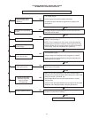
REMOVAL OF EXISTING BOILER FROM A COMMON VENTING SYSTEM
GENERAL MAINTENANCE
These boilers are designed to give many years of efficient and
satisfactory service when properly operated and maintained.
To assure continued good performance, the following
recommendations are made.
The area around the unit should be kept clean and free from lint and
debris. Sweeping the oor around the boiler should be done carefully.
This will reduce the dust and dirt which may enter the burner and
pilot air passages, causing improper combustion and sooting.
THE FLOW OF COMBUSTION AND VENTILATION AIR TO THE
BOILER MUST NOT BE OBSTRUCTED.
THE BOILER AREA MUST BE KEPT CLEAR AND FREE
FROM COMBUSTIBLE MATERIALS, GASOLINE, AND OTHER
FLAMMABLE VAPORS AND LIQUIDS.
Any safety devices including low water cutoffs used in conjunction
with this boiler should receive periodic (every six months) inspection
to assure proper operation. A low water cutoff device of the oat
type should be ushed every six months. All relief valves should be
inspected and manually operated at least twice a year. More frequent
inspections may be necessary depending on water conditions.
Periodic checks, at least twice a year, should be made for water
and/or gas leaks.
More frequent inspections may be necessary depending on
water conditions.
The boiler mounted gas and electrical controls have been designed to
give both dependable service and long life. However, malfunction can
occur, as with any piece of equipment. It is therefore recommended
that all components be checked periodically by a qualied serviceman
for proper operation.
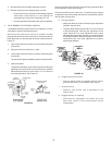
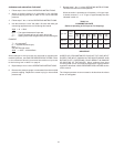
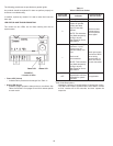
MANUAL RESET HIGH LIMIT SWITCH CONTINUITY TEST
Do not depress the switch reset button prior to testing. With the
unit cold, disconnect the leads from the switch. With a multimeter
place a probe on each side of the switch. If the meter reads zero
the switch is good. If you receive an innite or OL signal, the reason
could be:
1. Protector switch contacts open.
• Depress reset button on switch (switch cannot be reset until
water temperature in the boiler coils drop below 200°F). Meter
should read zero.
2. Defective switch or bad leads.
• With leads attached, depress the switch button. If the meter does
not read zero, the switch is defective and must be replaced.
RELIEF VALVE
The safety relief valve should be opened at least twice a year to
check its working condition. This will aid in assuring proper pressure
relief protection. Lift the lever at the top of the valve several times
until the valve seats properly and operate freely.
DANGER
THE WATER PASSING OUT OF THE VALVE DURING CHECKING
OPERATION MAY BE EXTREMELY HOT. BEFORE OPERATING
RELIEF VALVE MAKE SURE DRAIN LINE IS INSTALLED TO
DIRECT DISCHARGE TO A SAFE LOCATION SUCH AS AN OPEN
DRAIN, TO AVOID SCALDING OR WATER DAMAGE.
WARNING
SHOULD OVERHEATING OCCUR OR THE GAS SUPPLY FAIL
TO SHUT OFF, TURN THE MANUAL GAS CONTROL VALVE TO
THE APPLIANCE.