


52
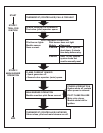
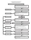
The following procedures are provided as a general guide.
Any module should be replaced if it does not perform properly on
checkout or troubleshooting.
In addition, replace any module if it is wet or looks like it has ever
been wet.
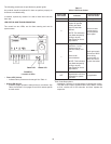
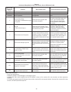
LED STATUS AND TROUBLESHOOTING
The control has two LEDs; one for ame sensing and one for
system status:
FIGURE 37.
Location of LEDs.
• Flame LED (Yellow)
– Indicates ame presence and strength. See Table 11.
• Status LED (Green)
– Indicates system operation status and error conditions. See
Table 12 and Table 13 on pages 53 and 54 for status specic
to each model.
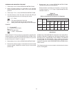
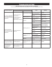
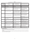
Table 11
Yellow LED Flame Codes
Yellow LED
Flash Code
a
Indicates
Recommended
Service Action
Heartbeat Normal Flame Signal not applicable
2
Weak Flame Signal-
Sytem will operate
reliably but ame
signal is less than
desired.
NOTE: This indication
may ash temporarily
during or shortly
after lightoff on some
applications.
Perform routine
maintenance to
assure optimum
ame signal.
1
Marginal Flame Signal
(less than 1.1µA)-
System may not
operate reliably over
time.
Service call
recommended.
NOTE: This indication
may ash temporarily
during or shortly
after lightoff on some
applications.
Check gas supply,
pilot burner, ame
sense wiring,
contamination of
ame rod, burner
ground connection.
OFF
No Flame or Flame
Signal below minimum
threshold for system
operation.
not applicable
a
Flash Code Descriptions:
- Heartbeat: Constant 1/2 second bright 1/2 second dim cycles.
- The ash code number signies that the LED ashes X times
at 2Hz, remains off for two seconds, and then repeats the
sequence.