


46
CLEANING AND FLUSHING INSTRUCTIONS
INTERNAL CONTAMINANTS
The hydronic system must be internally cleaned and flushed
after a new or replacement boiler has been installed to remove
contaminants that may have accumulated during installation.
This is doubly important when a replacement boiler is installed
into an existing system where Stop Leak or other boiler additives
have been used.
Failure to clean and flush the system can produce acid
concentrations that become corrosive, cause gases to form
that block water circulation or lead to formation of deposits on
the boiler surfaces, any of which could result in damage to the
system and circulator.
All hot water heating systems should be completely flushed with
a grease removing solution to assure trouble-tree operation.
Pipe joint compounds, soldering paste, grease on tubing and
pipe all tend to contaminate a system.
Failure to flush contaminates from a system can cause solids
to form on the inside of boiler exchangers, create excessive
amounts of air and other gases to block circulation, foul
various system accessories and even deteriorate circulation
seals and impellers.
It is recommended that after installation, the boiler and system
when filled should include the proper percentage of cleaning
solution related to approximate water volume of the system. Fire
and circulate for about one hour and then flush clean with fresh
water. Commercial grease removing solutions are available
from your distributor.
HOT WATER SUPPLY BOILERS PREVENTIVE MAINTENANCE
For care of the HW water system please refer to the A. O. Smith
Users Information Manual supplied with the Boiler.
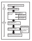
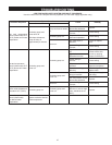
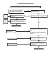
PRE-TROUBLESHOOTING
Before any extensive troubleshooting, perform the following:
Ensure that:
– Voltage (120 vac) is supplied to the appliance.
– System control (tank temperature control, thermostat, etc.)
is calling for appliance operation (call for heat).
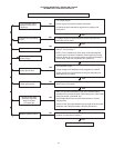
– Other contacts (switches) are closed (relay, low water cutoff,
ow switch, coil protector, pressure switch, etc.).
– Gas supply pressure is within the maximum and minimum
operating ranges listed on the appliance rating plate/label.
– Voltage (24 vac) is supplied by transformer.
– Appliance is wired according to wiring diagram.
Note: Cross wiring the 24 volt circuit of the relay will short the
transformer.
– All wire terminals/connectors are rmly attached to valves,
modules, switches, limit controls, etc.
– For LP models only check for possible lockout condition of
the the ignition module.