


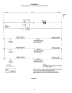
25
2. LINEAR-TEMP INSTALLATIONS
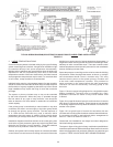
Control for these systems is decided mainly by the type of building
system controlling that is desired. A single boiler installation might
be controlled directly from space temperature thermostat(s).
Multiple boiler installations are more effective when the boilers are
sequenced in and out of operation by some form of main water
temperature controller. With one to three boilers, individual controls
set at progressive temperatures may be used. For more than three
or four boilers, a step controller is recommended.
Individual boiler controls, or the separate stages of a step controller,
should re a boiler and also start the boiler loop circulator whenever
the rst boiler of a group supplied by that boiler loop is red. Some
large installations may require the ring of more than one boiler
per stage.
The system or primary circulator may or may not be controlled
by the boiler sequencer. When this pump is operated through
the rst switch of any type of step controller, care should be
taken to determine if a motor starter is needed due to insufcient
switch capacity.
If the primary pump is controlled by a manual switch or any other
controllers, the electric current supply to the boiler group should
be through the primary pump controller. The fast response of
A. O. Smith boilers eliminates any need to maintain boiler
temperature when the system is satised. Wiring should always
prevent ring of boiler(s) when there is no water ow in the mains.
Installation diagrams show ow switches in the outlet piping from
each boiler as good protection against any boiler being red when
the boiler loop circulator is not in operation. These ow switches
will also serve as protection if there is a loss of water.
Outdoor vent systems will normally require an automatic shutdown
control if there is a continuous recirculating main and/or if the entire
building is not under control of space temperature thermostats. A
single bulb outdoor sensing control will prevent overheating of halls,
stairways or other uncontrolled areas. There are occasions when
outdoor temperatures are temporarily too warm for even a moderate
amount of heating in these areas.
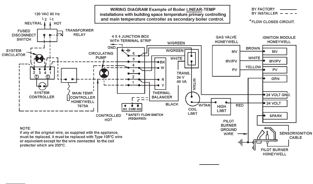
Space temperature controlling can be varied to meet the building
requirements. Either the single thermostat, as shown, or multiple
zone thermostats should control a common relay. This relay
controls electric power to the system primary circulator and
to the main water temperature controller. This provides for
water movement in the system before the main temperature
controller can start the secondary circulating pump or fire
the boiler.
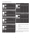
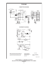
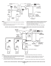
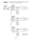
Figure 17 shows a typical wiring diagram for a single boiler space
heating installation. The boiler may be controlled by a main
temperature controller as shown or may include outdoor reset
if desired.
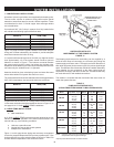
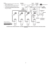
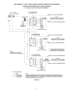
Figure 18 on page 26 shows a layout for various choices of controls
often found in commercial heating. These layouts are not intended
to be wiring diagrams and only show the relation of one device to
another in the system.
Figure 18 is a typical layout of controls for two boilers with one
circulator and including optional outdoor reset and thermal balancer.
If a secondary circulator is used with each boiler, arrangement for
boiler no. 2 will be as shown for boiler no. 1.
Commercial size installations are always best when designed to
individual building requirements.
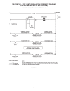
The layout in gure 18 is typical of many combination possibilities to
meet the requirements of different buildings. Brand names of controls
shown are suggestions and not directly related to any particular type
of system. THESE LAYOUTS ARE NOT WIRING DIAGRAMS.
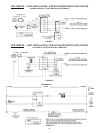
TYPICAL WIRING DIAGRAM (IID SYSTEM) FOR SINGLE BOILER LINEAR-TEMP
®
INSTALLATION
FIGURE 17.