


12
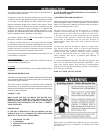
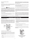
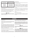
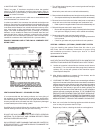
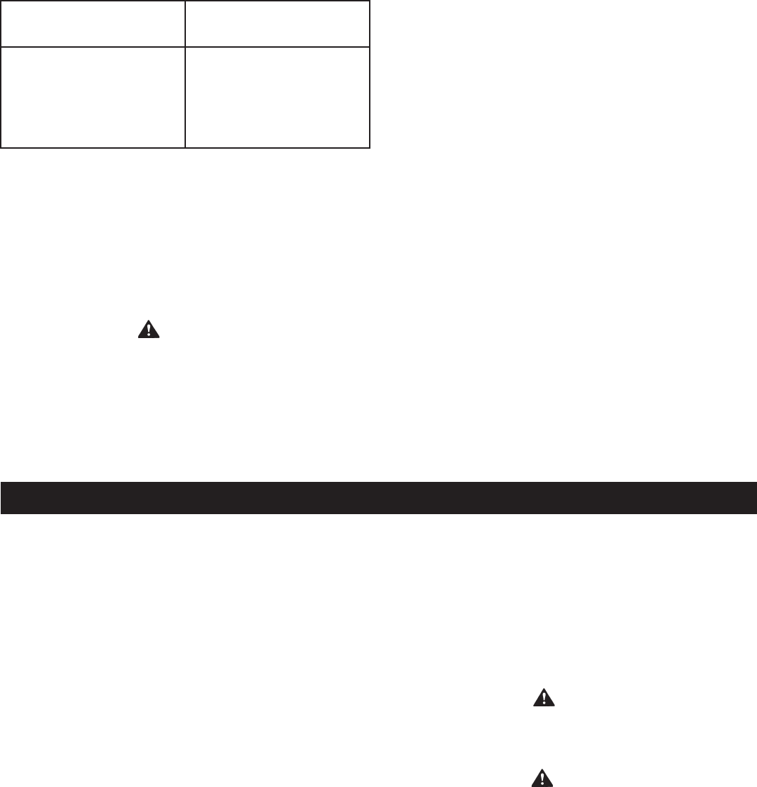
Water Temperature
Time to Produce 2nd & 3rd
Degree Burns on Adult Skin
OVER: 170°F (77°C)
160°F (71°C)
150°F (65°C)
140°F (60°C)
130°F (54°C)
120°F (49°C)
Nearly Instantaneous
About 1/2 second
About 1-1/2 seconds
Less than 5 seconds
About 30 seconds
More than 5 minutes
USE ANTI-SCALD VALVE(S) in the hot water system to reduce
the risks of scalds at points of use such as lavatories, sinks
and bathing facilities.
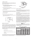
A change in water temperature in the storage tank lower than
the Tank Temperature Control setting will cause the sensor to
close its contacts and consequently energize the boiler.
If the Tank Temperature Control is out of calibration, replace it
with a new one; do not attempt to fix this control.
WARNING
SHOULD OVERHEATING OCCUR OR THE GAS SUPPLY FAIL
TO SHUT OFF, TURN OFF THE MANUAL GAS CONTROL
VALVE TO THE APPLIANCE.
GENERAL
THERMOMETERS
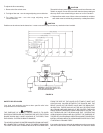
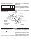
Thermometers should be obtained and field installed as shown
in the installation diagrams.
Thermometers are installed in the system as a means
of detecting a possible liming condition in the boiler.
An increase of 5°F (3°C) over the normal temperature
rise through the boiler is an indication that lime is
present. The term "temperature rise" designates
the difference between the boiler inlet and outlet water
temperature.
An increase of 5°F (3°C) above the recorded temperature
rise may signify a liming condition in the coils or heat
exc hange r. Refer to CLE AN ING AN D FLUS HI NG
section of this manual for deliming instructions.
Record temperature rise at initial start-up for future
reference.
DRAIN VALVE (Not Supplied)
A drain valve must be obtained and installed on each boiler
and tank for draining purposes, see installation diagrams in
this manual.
REQUIRED ABILITY
Installation or service of this boiler requires ability equivalent to that
of a licensed tradesman in the eld involved. Plumbing, air supply,
venting, gas supply and electrical work are required.
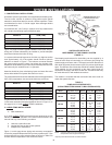
LOCATION
When installing the boiler, consideration must be given to proper
location. Location selected should be as close to the stack or chimney
as practicable with adequate air supply and as centralized with the
piping system as possible. This location should also be such that the
gas ignition system components are protected from water (dripping,
spraying, etc.) during appliance operation and service (circulator
replacement, control replacement, etc.).
THE BOILER MUST NOT BE INSTALLED ON CARPETING.
THE BOILER SHOULD NOT BE LOCATED IN AN AREA WHERE
IT WILL BE SUBJECT TO FREEZING.
LOCATE IT NEAR A FLOOR DRAIN. THE BOILER SHOULD BE
LOCATED IN AN AREA WHERE LEAKAGE FROM THE BOILER OR
CONNECTIONS WILL NOT RESULT IN DAMAGE TO THE ADJACENT
AREA OR TO LOWER FLOORS OF THE STRUCTURE.
WHEN SUCH LOCATIONS CANNOT BE AVOIDED, A METAL
DRAIN PAN SHOULD BE INSTALLED UNDER THE BOILER. Such
pans should be fabricated with sides at least 60mm (2-1/2") deep,
with length and width at least 50mm (2") greater than the diameter
of the boiler and must be piped to an adequate drain. The pan must
not restrict combustion air ow.
WARNING
KEEPING BOILER AREA CLEAR AND FREE FROM COMBUSTIBLE
MATERIALS, GASOLINE AND OTHER FLAMMABLE VAPORS AND
LIQUIDS.
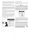
WARNING
THERE IS A RISK IN USING FUEL BURNING APPLIANCES
SUCH AS BOILERS IN ROOMS OR AREAS WHERE GASOLINE,
OTHER FLAMMABLE LIQUIDS OR ENGINE DRIVEN EQUIPMENT
OR VEHICLES ARE STORED, OPERATED OR REPAIRED.
FLAMMABLE VAPORS ARE HEAVY AND TRAVEL ALONG THE
FLOOR AND MAY BE IGNITED BY THE IGNITER OR MAIN BURNER
FLAMES CAUSING FIRE OR EXPLOSION. SOME LOCAL CODES