


21
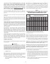
Use table 7, or CAN/CSA B149.1 (current edition) to
size iron pipe or equivalent gas supply line. Table 7
is based on a pressure drop of 0.3 inches of water and
a specific gravity of 0.60 approximately that of natural
gas. (LP gas has an S.G. of about 1.53). If the service pressure
is five inches water column or less, use one pipe size larger in
order to minimize pressure drop in the line.
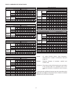
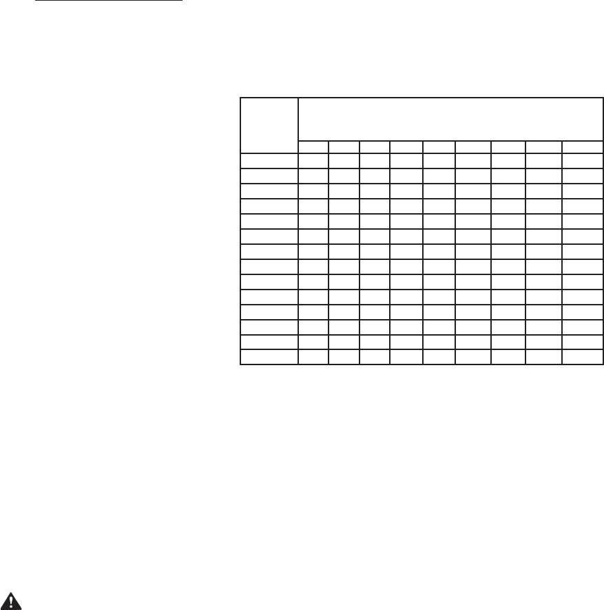
TABLE 7.
MAXIMUM CAPACITY OF PIPE IN CUBIC FEET OF GAS PER
HOUR (BASED UPON A PRESSURE DROP OF 0.3 INCH
WATER COLUMN AND 0.6 SPECIFIC GRAVITY GAS)
Distance
from Gas
Meter
Nominal Iron Pipe Size (Inches)
1/2 3/4 1 1 1/4 1 1/2 2 2 1/2 3 4
10 (3) 132 278 520 1,050 1,600 3,050 4,800 8,500 17,500
20 (6) 92 190 350 730 1,100 2,100 3,300 5,900 12,000
30 (9) 73 152 285 590 890 1,650 2,700 4,700 9,700
40(12) 63 130 245 500 760 1,450 2,300 4,100 8,300
50 (15) 56 115 215 440 670 1,270 2,000 3,600 7,400
60 (18) 50 105 195 400 610 1,150 1,850 3,250 6,800
70 (21) 46 96 180 370 560 1,050 1,700 3,000 6,200
80 (24) 43 90 170 350 530 990 1,600 2,800 5,800
90 (27) 40 84 160 320 490 930 1,500 2,600 5,400
100 (30) 38 79 150 305 460 870 1,400 2,500 5,100
125 (38) 34 72 130 275 410 780 1,250 2,200 4,500
150 (45) 31 64 120 250 380 710 1,130 2,000 4,100
175 (53) 28 59 110 225 350 650 1,050 1,850 3,800
200 (60) 26 55 100 210 320 610 980 1,700 3,500
*The heating value of Natural Gas is approximately 1,050 Btu/Ft
.3
.
Propane (LP) Gas has a heating value of approximately 2,500 Btu/Ft
3
.
1 cu. meter=35.31 cu. feet.
Where it is necessary to use more than the average number of pipe
ttings i.e. elbows, tees, and valves in gas supply line, use a pipe
larger than specied to compensate for increased pressure drop.
2B. SIZING GAS SUPPLY LINE (For multiples of over three boilers of
same size or for multiple installations of two or more mixed sizes).
Capacities in cubic feet per hour of 0.60 specic gravity gas for
different sizes and lengths are shown in table 7. No additional
allowance is necessary for an ordinary number of ttings.
Applications of the gravity factor converts the gures given in table
7 to capacities with another gas of different specic gravity. Such
application is accomplished by multiplying the capacities given in
table 7 by the multipliers shown in table 8 on page 22.
To determine the size of each section of gas piping in a system within
the range of table 7 proceed as follows:
• Determine the gas demand of each appliance to be attached
to the piping system. When table 7 is to be used to select the
piping size, calculate the gas demand in terms of cubic feet
per hour for each piping system outlet. The gas demand for
an appliance can be found by dividing its heat input rate by
the gas’s heating value.
• Obtain or determine the length of piping from the gas meter or
service regulator to the appliance(s).
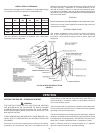
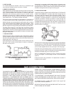
TO TRAP ANY DIRT OR FOREIGN MATERIAL IN THE GAS
SUPPLY LINE, A DIRT LEG (SOMETIMES CALLED DRIP
LEG or sediment trap) MUST BE INCORPORATED IN THE
PIPING, see Figure 1 on page 6. The dirt leg must be readily
accessible and not subject to freezing conditions. INSTALL IN
ACCORDANCE WITH RECOMMENDATIONS OF SERVING
GAS SUPPLIERS. (Refer to National Fuel Gas Code, ANSI
Z223.1 or CAN/CSA-B 149.1 Installation Codes.
To prevent damage, care must be taken not to apply too
much torque when attaching gas supply pipe to the gas valve
gas inlet.
Fittings and unions in the gas line must be the metal to
metal type.
Apply joint compounds (pipe dope) sparingly and only to the
male threads of pipe joints. Do not apply compound to the first
two threads. Use compounds resistant to the action of liquefied
petroleum gases.
THE BOILER AND ITS GAS CONNECTIONS MUST BE LEAK
TESTED BEFORE PLACING THE BOILER IN OPERATION.
Use soap and water solution or other material acceptable for
the purpose in locating gas leaks. DO NOT USE MATCHES,
CANDLES, FLAME OR OTHER SOURCES OF IGNITION FOR
THIS PURPOSE.
DISCONNECT THE BOILER AND ITS MAIN MANUAL
GAS SHUTOFF VALVE FROM THE GAS SUPPLY PIPING
SYSTEM DURING ANY PRESSURE TESTING OF THE GAS
SUPPLY SYSTEM OVER 1/2 PSIG (3.5kPa). THE GAS SUPPLY
LINE MUST BE CAPPED WHEN NOT CONNECTED TO
THE BOILER.
THE BOILER MUST BE ISOLATED FROM THE GAS SUPPLY
PIPING SYSTEM BY CLOSING ITS MAIN MANUAL GAS
SHUTOFF VALVE DURING ANY PRESSURE TESTING OF
THE GAS SUPPLY PIPING SYSTEM AT TEST PRESSURES
EQUAL TO OR LESS THAN 1/2 PSIG (3.5kPa).
PURGING AND SIZING
Gas line purging is required with new piping or systems in which
air has entered.
CAUTION
PURGING SHOULD BE PERFORMED BY PERSONS
EXPERIENCED IN THIS TYPE GAS SERVICE TO AVOID RISK OF
FIRE OR EXPLOSION. PURGE DISCHARGE MUST NOT ENTER
CONFINED AREAS OR SPACES WHERE IGNITION CAN OCCUR.
THE AREA MUST BE WELL VENTILATED AND ALL SOURCES OF
IGNITION MUST BE INACTIVATED OR REMOVED.
1. CORRECT GAS
Make sure the gas on which the boiler will operate is the same as
that specied on the boiler rating plate. Do not install the boiler if
equipped for a different type gas — consult your supplier.
2A. SIZING GAS SUPPLY LINE (For single boiler installations
and for installations of multiples of two or three of same
size boilers).