


19
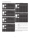
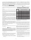
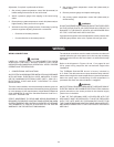
NO. SUGGESTED ITEMS FOR INSTALLATION
1
Short pipe nipple and pair of boiler loop tees in piping
between system supply and return. One set per each group
of boilers.
2 Boiler pipe loop. See piping sizing data.
3 Boiler circulator. See pump sizing data.
4 Thermometer.
5 Theraltimeter.
6 Plug cock to control ow rate.
7
Safety ow switches. For interlock with other systems or
instead of low water cutoff.
8 Relief valve.
9
With one -300, -399 or -420 item 9 is - sensing element of
remote control.
With a group of -300's, -399's or -420's, item 9 is - for 1st
boiler, the sensing element as above. For additional boilers,
install a 2nd limit control if required by local codes. With
any -520, -610 or 670 boilers, install 2nd limit control here if
required by local code.
BOILER INLET - OUTLET SIZES
10
HW-300 - 1-1/4", HW-399 - 1-1/2", HW-420 - 1-1/2",
HW-520 & HW-610 - 2".
10
HW-300 - 1-1/4", HW-399 - 1-1/2", HW-420 - 1-1/2", HW-520
& HW-670 - 2".
MINIMUM BRANCH SIZES TO BOILERS
11
HW-300 - 1-1/4" HW-520, 610 (Single boiler
HW-399 - 1-1/2" per pump) 2"
HW-420 - 1-1/2"
11
HW-300 - 1-1/4" HW-520, 670 (Single boiler
HW-399 - 1-1/2" per pump) 2"
HW-420 - 1-1/2"
12
Flow control valve. Required only if ow rate of system
primary is excessive for size of boiler branch tees or if chilled
water main is above boilers.
13 System supply temperature thermometer.
14
Boiler headers for three (3) boilers can be larger than pipe
loop, if desired, to aid in balancing.
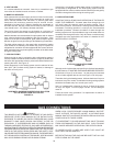
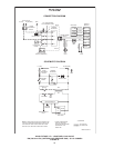
The system flow rate is selected to give the desired system
temperature drop - depending on the design criteria.
The boiler generator ow rates, on the other hand, should be
selected to give the temperature rise through the generator that is
both economical and offers the best generator efciency.
The boiler temperature rise is normally between 10
0
C and 20
0
C (20
0
F
and 40
0
F). The system temperature that will be introduced to the
boiler (inlet temperature) plus the selected boiler temperature rise
selected from PUMP AND PIPE SIZING DATA should not exceed
the high limit control setting of 115
0
C (240
0
F).
There should be a relation of the minimum system load to the size
boiler selected as the rst ring or base boiler. This will stabilize
operation during minimum load periods.
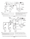
B. Commercial Boiler Replacements
Application of LINEAR-TEMP
®
to a commercial boiler replacement
with an old multiple pump installation is an excellent way to modernize
the system. The A. O. Smith boiler(s) should be installed on a pipe
loop with a separate circulating pump selected from PUMP AND
PIPE SIZING DATA TABLE.
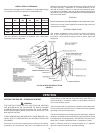
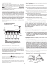
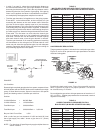
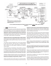
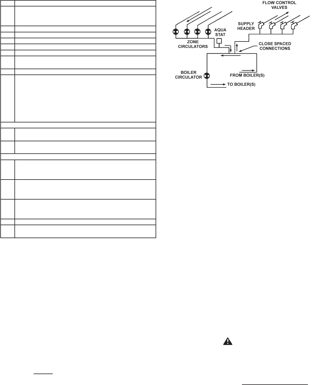
Figure 12 shows a line drawing of how the system headers should be
connected to the pipe loop installed with the replacement boiler(s).
Make-up water connections and accessories are not shown.
SCHEMATIC OF THE LINEAR-TEMP
®
SYSTEM
FIGURE 12.
Supply and return headers of the old system should be connected
to the boiler loop with a pair of tees set close together. The boiler
loop pump and the boiler(s) should be wired to operate only when
any of the system pumps are in operation. The number of zone
pumps that may be in operation at any particular time will take
their required ow rate out from the rst tee in the boiler piping.
This water will be circulated through the proper branches from
the supply header to the zones calling for heat. The water will be
brought back to the return header and then into the second tee in
the boiler pipe loop. There will be no conict between the boiler
pump and the zone pumps when the two tees in the boiler loop
are placed close together.
Normal use of ow control valves is required to prevent cross
circulation of zones as with any multiple pump system. Flow control
is not required on boiler circuit.
Attention should be given to balancing gas inputs and water ow
rates. Large systems with multiple boilers should include main water
temperature control (with or without outdoor reset) to stage the boilers
on and off in relation to the load on the system.
3. WATER SUPPLY LINE
These boilers can be used ONLY in a forced circulation hot water
heating system. Since most forced circulation systems will be of
the closed type, install the water supply line as shown on piping
diagrams, Figure 7 to 11 on pages 14 and 18.
Fast lling of large pipe, old radiator installations and pressure
purging of series loop systems (where high pressures are not
available) requires bypassing of the pressure reducing valve.
Generally, pressure purging is not possible with a well pump system.
High point air venting is essential.
If the system is of the open type, a pressure reducing valve
will not be required as the water supply to the system will be
controlled by a manually operated valve. An overhead surge
tank is required.
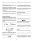
4. EXPANSION TANK
CAUTION
A closed system will exist if a check valve (without bypass), pressure
reducing valve (without bypass), or a water meter (without bypass) is
installed in the cold water line between the water heater and street
main (or well).
Excessive pressure may develop causing premature tank failure or
intermittent relief valve operation. This is not a warranty failure. An
expansion tank or a similar device may be required in the inlet supply
line between the appliance and the meter or valve to compensate for
the thermal expansion of water under supply pressure, see Figure 7
on page 14.
An air separator as shown in the piping diagrams is recommended
especially for modern commercial hydronic systems.