


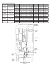
10
CAUTION
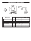
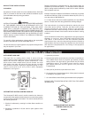
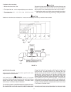
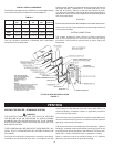
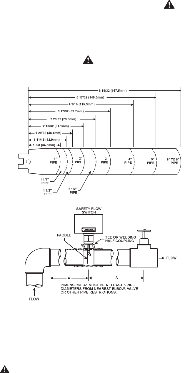
Paddle must be trimmed at the dotted arc. It must not touch the pipe or have any restriction when installed.
FIGURE 6.
To adjust the ow rate setting:
1. Remove the ow switch cover.
2. For higher ow rate - turn the range adjusting screw clockwise.
3. For lower flow rate - turn the range adjusting screw
counterclockwise.
CAUTION
The switch is factory set at approximately the minimum ow rate, see
Table 3 on page 9. It must not be set lower than the factory setting as
this may result in the switch failing to return at 'no ow' condition.
4. Replace ow switch cover. Where units are installed in multiples,
each boiler must be individually protected by a safety ow switch.
SAFETY RELIEF VALVES
Your local code authority may have other specic relief valve
requirements not covered below.
WARNING
THE PURPOSE OF A SAFETY RELIEF VALVE IS TO AVOID
EXCESSIVE PRESSURE OR TEMPERATURE INTO THE STEAM
RANGE WHICH MAY CAUSE SCALDING AT FIXTURES, TANK
EXPLOSION, SYSTEM OR BOILER DAMAGE.
TO AVOID SCALDING OR WATER DAMAGE A DRAIN LINE MUST
BE CONNECTED TO A RELIEF VALVE TO DIRECT DISCHARGE
TO A SAFE LOCATION. A DRAIN LINE MUST NOT BE REDUCED
FROM THE SIZE OF THE VALVE OUTLET AND IT MUST NOT
CONTAIN ANY VALVES BETWEEN THE BOILER AND THE
RELIEF VALVE OR THE RELIEF VALVE AND THE DRAIN EXIT.
IN ADDITION, THERE SHOULD NOT BE ANY RESTRICTIONS
IN A DRAIN LINE NOR SHOULD IT BE ROUTED THROUGH
AREAS WHERE FREEZING CONDITIONS MIGHT OCCUR. DO
NOT THREAD OR CAP THE DRAIN LINE EXIT. RESTRICTING
OR BLOCKING A DRAIN LINE WILL DEFEAT THE PURPOSE OF
THE RELIEF VALVE AND MAY CREATE AN UNSAFE CONDITION.
INSTALL A DRAIN LINE WITH A DOWNWARD SLOPE SUCH THAT
IT NATURALLY DRAINS ITSELF.
If any safety relief valve is replaced, the replacement valve must comply
with the current editions of the ASME Boiler and Pressure Vessel