


15
Building materials must not come in contact with combustion
products from stack or chimney, due to the degradating properties
of ue products.
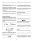
Flue products must have a minimum clearance of 4 feet (1.22m)
horizontally from, and in no case above or below, unless a 4-foot
(1.22m) horizontal distance is maintained, from electric meters, gas
meters, regulators and relief equipment.
CAN/CSA B149.1, Installation Code species a 6 foot horizontal
vent terminal clearance to gas and electric meters and relief devices
(this clearance is specied as 4 feet in the U.S. under the National
Fuel Gas Code, ANSI/Z223.1). Therefore instruction, which species
compliance with the 4 foot clearance, as applies in the U.S. only, and the
CAN/CSA B149.1 Installation Code applies in Canada.
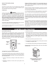
1. DRAFT HOOD
The draft hood furnished with this boiler must be installed without
alteration. Provision must be made if the boiler is installed in conned
space or a small boiler room to accommodate draft hood spillage and
avoid risks described above. The upper air opening called for in the
AIR REQUIREMENTS section of this manual is for this purpose.
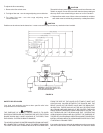
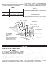
2. VENT CONNECTION
Size and install proper size vent pipe. Do not reduce pipe size to
less than that of the draft hood outlet.
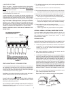
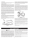
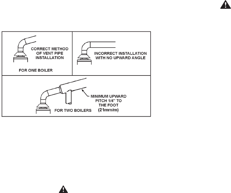
Horizontal runs of vent pipe shall be securely supported by
adequately placed (approximately every 4 feet or 1 meter), non-
combustible hangers and/or slip joints suitable for the weight
and design of the materials employed to prevent sagging and
to maintain a minimum upward slope of 1/4" (21mm/m) per foot
from the boiler to the vent terminals, see Figure 8. Dampers or
other obstructions must not be installed in the vent. Be sure
that the vent pipe does not extend beyond the inside wall of
the chimney.
VENT PIPE INSTALLATION
FIGURE 8.
Where a continuous or intermittent back draft is found to exist the
cause must be determined and corrected. A special vent cap may
be required. If the back draft cannot be corrected by the normal
methods or if a suitable draft cannot be obtained, a blower type
ue gas exhauster may be employed to ensure proper venting and
correct combustion if permitted by local codes.
WARNING
FAILURE TO CORRECT BACK DRAFTS WILL CAUSE AIR
CONTAMINATION AND UNSAFE CONDITIONS.
Vent connectors serving appliances vented by natural draft shall not
be connected into any portion of mechanical draft systems operating
under positive pressure.
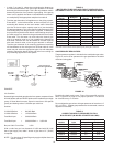
3. CONNECTING BOILER TO A COMMON VENT
Do not connect the boiler to a common vent or chimney with solid
fuel burning equipment. This practice is prohibited by many local
building codes as is the practice of venting gas red equipment to
the duct work of ventilation systems.
Where a separate vent connection is not available and the vent pipe
from the boiler must be connected to a common vent with oil burning
equipment, the vent pipe should enter the common vent or chimney
at a point ABOVE the ue pipe from the oil red unit.
Where two or more appliances vent into a common vent connector
or manifold, the area of the common vent or vent connector should
at least equal the area of the largest vent connector plus 50% of the
areas of the additional draft hood outlets.
When removing a boiler from a system with a common vent, use
the following steps:
Be sure the other appliances connected to the common vent are
not in operation.
Seal any unused openings in the common venting system.
Visually inspect the venting system for proper size and horizontal pitch
and determine there is no blockage or restriction, leakage, corrosion
and other deciencies which could cause an unsafe condition.
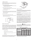
WARNING
Ensure sufcient supply and ventilation air. Under no circumstances
should the equipment room where the boiler is installed ever be under
negative pressure. Insufcient air supply can interfere with combustion
and ventilation of this boiler resulting in unsafe conditions.
Insofar as is practical, close all building doors and windows and
all doors between the space in which the appliances remaining
connected to the common venting system are located and other
spaces of the building. Turn on clothes dryers and any appliance not
connected to the common venting system. Turn on any exhaust fans,
such as range hoods and bathroom exhausts, so they will operate
at maximum speed. Close replace dampers.
Place in operation the appliance being inspected. Follow the
lighting instructions. Adjust thermostat so appliance will operate
continuously.
Test for spillage at the draft hood relief opening after ve minutes of
main burner operation. Use the ame of a match or candle.
After it has been determined that each appliance remaining connected
to the common venting system properly vents when tested as outlined
above, return doors, windows, exhaust fans, replace dampers and
any other gas burning appliance to their previous conditions of use.
Any improper operation of the common venting system should be
corrected so the installation conforms with the current edition of
CAN/CSA B149.1 (current edition). When resizing any portion of
the common venting system, the common venting system should
be resized to approach the minimum size as determined using the
appropriate tables in CAN/CSA B149.1.