


40
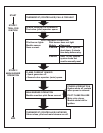
4. Reinstall the burner manifold assembly on boiler.
5. Restore electrical power and gas supply to boiler.
• Put the boiler back in operation by following the lighting
instructions in this manual or on the lighting and
operating label on the boiler. See pages 43 - 44.
• Check for gas leaks and proper boiler and vent operation.
2. PILOT BURNER - ELECTRONIC IGNITION
To establish pilot ame without main burner operation, it will be
necessary to perform the following steps:
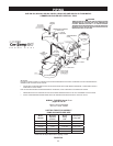
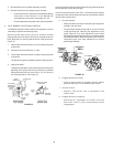
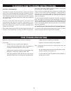
Servicing of the pilot burner (every six months) includes
keeping pilot shield (not shown) free of lint, cleaning the burner
head, the primary air opening and the orice of the pilot burner,
Figure 35.
1. Open fused disconnect switch or shut off electrical power
to the boiler.
2. Disconnect wire from MV wire on valve.
3. Close fused disconnect switch to restore electrical power
to the boiler.
The pilot will now ignite provided the system is calling for heat.
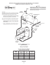
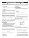
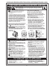
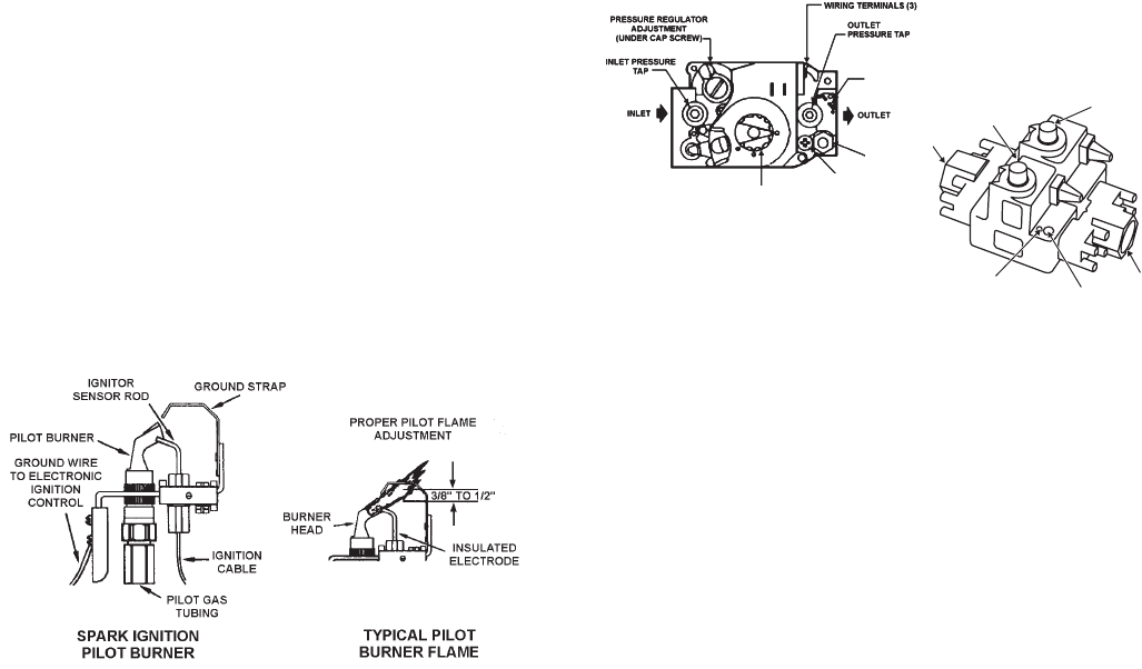
4. Adjust pilot ame.
To adjust the pilot ame, remove the cap screw from the pilot
adjusting screw (Figure 36) and turn to deliver a sufcient
ame at the pilot burner to cover 3/8" to 1/2" (10-12mm) of
the sensing probe tip. See Figure 35.
FIGURE 35.
Check for good terminal connection at the sensing probe at the pilot
burner assembly if pilot does not light.
Check for electrical power to the valve. If electrical power and gas
are present at the valve and the pilot does not operate when system
calls for heat, replace valve.
5. Low gas pressure
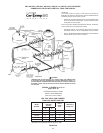
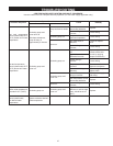
• Adjust pilot ame by means of the pilot gas adjustment
located in the gas valve.
• The pilot ame should envelop 3/8 to 1/2 inch of the tip
of the thermocouple. Remove pilot adjustment cover
screw, Figure 36. Turn inner adjustment screw or pilot
adjusting valve clockwise to decrease, or counterclockwise
to increase pilot ame. Be sure to replace cover screw on
combination gas valve after adjustment to prevent
possible gas leakage.
GROUND
TERMINALS (2)
PILOT
OUTLET
GAS
CONTROL
PILOT ADJUSTMENT
(UNDER CAP SCREW)
PILOT SUPPLY
OUTLET
INLET
GAS VALVE KNOB
PRESSURE REGULATOR
ADJUSTMENT
PILOT ADJUSTMENT
UNDER SCREW
FIGURE 36.
6. Clogged pilot burner orice.
• Clean or replace orifice. A clogged orifice will restrict
gas flow and result in low thermocouple output.
7. Incorrect orifice.
• Replace. The Orifice size is stamped on the
wrench flats.
8. Clogged primary air opening.
• Restricted air passages will soften the pilot
flame and result in poor thermocouple flame
impingement.