


16
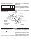
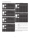
4. MULTIPLE VENT TABLE
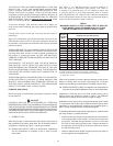
Table 5 on page 17 has been compiled to show the material
sizes in a Type B doublewall combined vent system. Refer to
CAN/CSA B149 .1 (current edition), or the ASHRAE 1983 Equipment
Volume for further information.
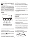
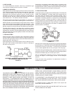
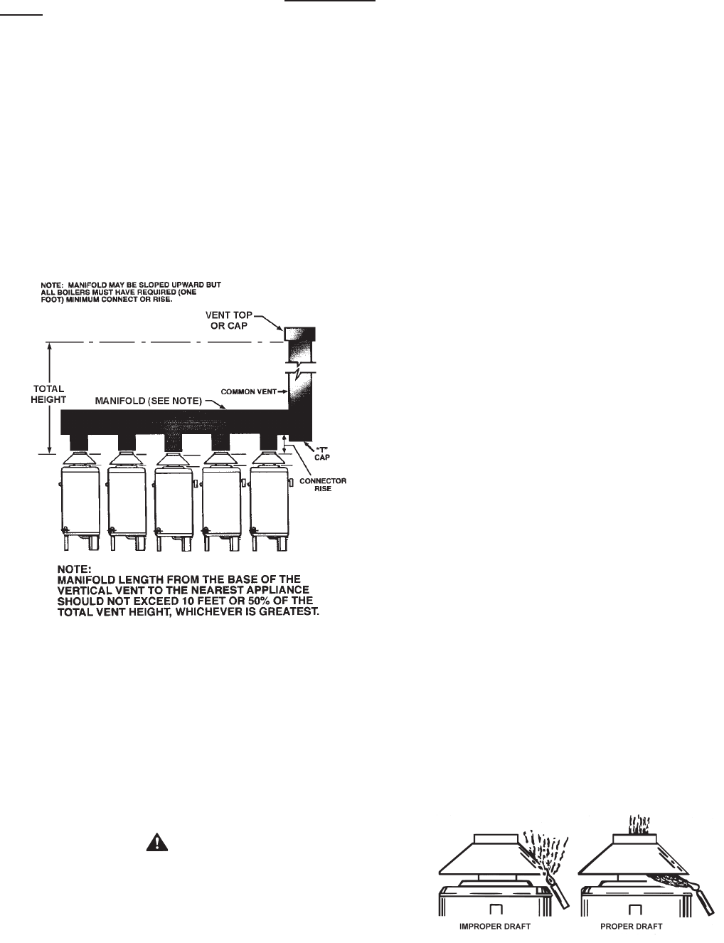
A combined vent system is one in which two or more boilers at one
level are attached to a common vent.
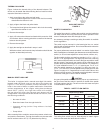
In order to use table 5, the connector rise and total vent height must
be known. Connector rise is vertical distance from the draft hood outlet
to the point where the manifold connection is made. Total vent height
is the least vertical distance from a draft hood outlet to the top of the
vent. Local codes or utility requirements often govern termination
height. ULC listed doublewall gas vents, up through 24" (610mm)
diameter, can be installed in heated and unheated areas and can
pass through oors, ceilings, partitions, walls and roofs, provided
the required one inch clearance is observed. These vents should be
installed in accordance with CAN/CSA B149.1 (current edition).
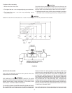
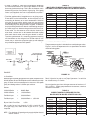
EXAMPLE SHOWING USE OF THE HW-610 COMBINED VENT
SIZING TABLE
FIGURE 9.
VENTING MAINTENANCE - STANDARD VENTING
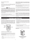
It is recommended that the heating surfaces and vent piping of
the appliance be checked every six months for dust, deterioration
and carbon deposits. Remove all soot or other obstructions from
chimney and ue which will retard free draft. Replace any damaged
or deteriorated parts of the venting system.
Qualied servicers should follow this procedure when the boiler’s
external heating surfaces and vent pipe need cleaning.
CAUTION
DO NOT USE A NYLON BRUSH OR OTHER STATIC CREATING
MATERIAL TO CLEAN DUST AND CARBON DEPOSITS FROM
HEATING SURFACES AND VENT.
SUCH DEPOSITS ARE FLAMMABLE AND MAY BE IGNITED BY
STATIC ELECTRICITY. USE A METAL BRUSH TO MINIMIZE THE
DANGER OF EXPLOSION.
1. Turn off the electrical power (main manual gas shutoff and pilot
valves, if applicable).
Allow boiler parts and vent to cool before disassembly.
2. Remove the boiler draft diverter and vent pipe running to the chimney.
• Check parts and chimney for obstructions and clean as necessary.
3. Remove burner from boiler and other metal parts as required to
clean and vacuum the heat exchanger and combustion coils.
• Refer to parts list supplied with this manual for disassembly aid.
4. Reinstall the parts removed in steps 2 and 3.
• Be sure the vent pipe has a minimum upward pitch of one quarter
inch per foot of length (21mm/m) and is sealed as necessary.
5. Restore electrical power and gas supply to boiler.
• Place boiler in operation by following the lighting instructions
in this manual.
• Check for gas leaks and proper boiler and vent operation.
VENTING - SIDEWALL (OPTIONAL) POWER VENT SYSTEM
If you are installing the optional Power Vent Kit, refer to your
HW Power Vent Kit Installation Instructions for proper wiring
and installation procedures. Contact your local A. O. Smith
representative for details.
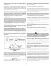
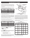
VENTING SYSTEM
HAVE VENTING SYSTEM CHECKED EVERY SIX MONTHS FOR
OBSTRUCTIONS AND/OR DETERIORATION IN VENT PIPING.
A. Insofar as is practical, close all doors, windows and air inlets to
the building. Turn on all exhaust fans (range hood, bathroom
exhaust, etc.) so they will operate at their maximum speed.
Close replace dampers.
B. After allowing appliance to operate for ve minutes, test for
spillage at the draft hood relief opening.
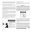
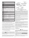
C. “CHECKING THE DRAFT. Operate vent connected gas utilization
equipment for several minutes and check to see that the combustion
products are going up the chimney or gas vent properly by passing
a lighted match or taper around the edge of the relief opening of
the draft hood. If the chimney or gas vent is drawing properly, the
match ame will be drawn into the draft hood. If not, the combustion
products will tend to extinguish this ame. IF THE COMBUSTION
PRODUCTS ARE ESCAPING FROM THE RELIEF OPENING OF
THE DRAFT HOOD, DO NOT OPERATE THE EQUIPMENT UNTIL
PROPER ADJUSTMENT OR REPAIRS ARE MADE TO PROVIDE
ADEQUATE DRAFT THROUGH THE CHIMNEY OR GAS VENT.”
D. Next, turn on all other fuel burning appliances within the same
room so they will operate at their full input.
Repeat step C above, checking the draft on each appliance.
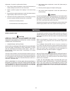
FIGURE 10.