


8
construction, the clearance between the door and door frame is
usually adequate to satisfy this ventilation requirement.
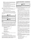
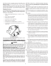
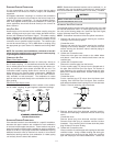
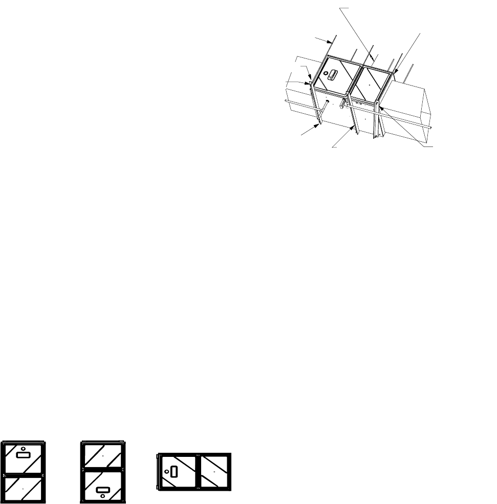
FURNACE SUSPENSION
If suspending the furnace from rafters or joists, use 3/8" threaded
rod and 2”x2”x1/8” angle iron as shown below. The length of rod
will depend on the application and the clearances necessary.
TILT OUTWARD TO ALLOW FOR
DOOR AND CIRCULATOR BLOWER
REMOVAL
3/8" DIAMETER
THREADED ROD
(6 PLACES)
PROVIDE 8" MINMUM CLEARANCE BETWEEN
CENTER ROD AND FURNACE CABINET
TO ALLOW FOR CIRCULATOR BLOWER REMOVAL
ASSURE FURNACE IS LEVEL FROM
END TO END AND HAS A SLIGHT
FORWARD TILT WITH THE FRONT
OF THE FURNACE 0"-3/4"
BELOW THE BACK OF THE FURNACE
POSITION AS CLOSE AS POSSIBLE
TO BLOWER DECK TO ALLOW FOR
CIRCULATOR BLOWER REMVOAL
2"
X
2"
X
1/8" ANGLE IRON
(3 PLACES)
HOLD DOWN
NUTS
SUPPORT
NUTS
Suspended Furnace
EXISTING FURNACE REMOVAL
NOTE: When an existing furnace is removed from a venting system
serving other appliances, the venting system may be too large to
properly vent the remaining attached appliances.
The following vent testing procedure is reproduced from the American
National Standard/National Standard of Canada for Gas-Fired Cen-
tral Furnaces ANSI Z21.47b-2002, CSA-2.3b-2002 Section 1.23.1.
The following steps shall be followed with each appliance connected to the
venting system placed in operation, while any other appliances con-
nected to the venting system are not in operation:
a. Seal any unused openings in the venting system;
b. Inspect the venting system for proper size and horizontal pitch, as
required by the National Fuel Gas Code, ANSI Z223.1 or the CSA
B149 Installation Codes and these instructions. Determine that there
is no blockage or restriction, leakage, corrosion and other deficien-
cies which could cause an unsafe condition;
c. In so far as practical, close all building doors and windows and all
doors between the space in which the appliance(s) connected to the
venting system are located and other spaces of the building. Turn on
clothes dryers and any appliance not connected to the venting sys-
tem. Turn on any exhaust fans, such as range hoods and bathroom
exhausts, so they shall operate at maximum speed. Do not operate a
summer exhaust fan. Close fireplace dampers;
d. Follow the lighting instructions. Place the appliance being inspected
in operation. Adjust thermostat so appliance shall operate continu-
ously;
e. Test for draft hood equipped spillage at the draft hood relief opening
after 5 minutes of main burner operation. Use the flame of a match
or candle;
f. After it has been determined that each appliance connected to the
venting system properly vents when tested as outlined above, re-
turn doors, windows, exhaust fans, fireplace dampers and any other
gas burning appliance to their previous conditions of use;
g. If improper venting is observed during any of the above tests, the
common venting system must be corrected.
halogen type refrigerants
cleaning solutions (such as perchloroethylene)
printing inks
paint removers
varnishes
hydrochloric acid
cements and glues
antistatic fabric softeners for clothes dryers
and masonry acid washing materials
• Seal off a non-direct vent furnace if it is installed near an
area frequently contaminated by any of the above
substances. This protects the non-direct vent furnace
from airborne contaminants. To ensure that the
enclosed non-direct vent furnace has an adequate supply
of combustion air, vent from a nearby uncontaminated
room or from outdoors. Refer to the Section V,
Combustion and Ventilation Air Requirements for details.
• If the furnace is used in connection with a cooling unit,
install the furnace upstream or in parallel with the cooling
unit. Premature heat exchanger failure will result if the
cooling unit is placed ahead of the furnace.
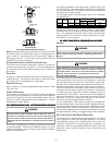
• If the furnace is installed in a residential garage, position
the furnace so that the burners and ignition source are
located not less than 18 inches (457 mm) above the floor.
Protect the furnace from physical damage by vehicles.
• If the furnace is installed horizontally, the furnace access
doors must be vertical so that the burners fire horizontally
into the heat exchanger. Do not install the unit with the
access doors on the “up/top” or “down/bottom” side of
the furnace.
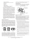
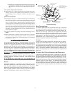
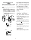
CLEARANCES AND A CCESSIBILITY
Installations must adhere to the clearances to combustible mate-
rials which this furnace has been design certified to. The mini-
mum clearance information for this furnace is provided on the unit’s
clearance label. These clearances must be permanently main-
tained. Clearances must also accommodate an installation’s gas,
electrical, and drain trap and drain line connections. If the alternate
combustion air intake or vent/flue connections are used additional
clearance must be provided to accommodate these connections.
Refer to Section IX, Vent Flue Pipe and Combustion Air Pipe for
details. NOTE: In addition to the required clearances to combus-
tible materials, a minimum of 24 inches service clearance must be
available in front of the unit.
TOP
BOTTOM
SIDE SIDE SIDE
TOP
BOTTOM
Upflow Counterflow Horizontal
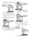
A furnace installed in a confined space (i.e., a closet or utility room)
must have two ventilation openings with a total minimum free area
of 0.25 square inches per 1,000 BTU/hr of furnace input rating.
Refer to Product Data Book applicable to your model* for minimum
clearances to combustible surfaces. One of the ventilation open-
ings must be within 12 inches of the top; the other opening must be
within 12 inches of the bottom of the confined space. In a typical
*NOTE: Please contact your distributor or our website for the applicable
product data book referred to in this manual.