


24
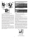
Inlet gas supply pressures must be maintained within the ranges
specified below. The supply pressure must be constant and avail-
able with all other household gas fired appliances operating. The
minimum gas supply pressure must be maintained to prevent
unreliable ignition. The maximum must not be exceeded to pre-
vent unit overfiring.
Propane Gas
Natural Gas
Inlet Gas Supply Pressure
Minimum:5.0" W.C. Maximum :10.0" W.C.
Minimum:11.0" W.C. Maximum :13.0" W.C.
HIGH ALTITUDE DERATE
When this furnace is installed at high altitude, the appropriate High
Altitude orifice kit must be applied. This is required due to the
natural reduction in the density of both the gas fuel and combus-
tion air as altitude increases. The kit will provide the proper design
certified input rate within the specified altitude range.
High altitude kits are purchased according to the installation alti-
tude and usage of either natural or propane gas. Contact your
distributor for a tabular listing of appropriate altitude ranges and
corresponding manufacturer’s high altitude (Natural, propane gas,
and/or Pressure Switch) kits.
Do not derate the furnace by adjusting the manifold pressure to a
lower pressure than specified on the furnace rating plate. The
combination of the lower air density and a lower manifold pressure
will prohibit the burner orifice from drawing the proper amount of
air into the burner. This may cause incomplete combustion, flash-
back, and possible yellow tipping.
In some areas the gas supplier may artificially derate the gas in an
effort to compensate for the effects of altitude. If the gas is artifi-
cially derated, the appropriate orifice size must be determined
based upon the BTU/ft
3
content of the derated gas and the altitude.
Refer to the National Fuel Gas Code, NFPA 54/ANSI Z223.1, and
information provided by the gas supplier to determine the proper
orifice size.
A different pressure switch may be required at high altitude regard-
less of the BTU/ft
3
content of the fuel used. Contact your distributor
for a tabular listing of appropriate altitude ranges and correspond-
ing manufacturer’s pressure switch kits.
PROPANE GAS CONVERSION
WARNING
P
OSSIBLE PROPERTY DAMAGE, PERSONAL INJURY OR DEATH MAY OCCUR IF
THE CORRECT CONVERSION KITS ARE NOT INSTALLED.
T
HE APPROPRIATE KITS
MUST BE APPLIED TO INSURE SAFE AND PROPER FURNACE OPERATION.
A
LL
CONVERSIONS MUST BE PERFORMED BY A QUALIFIED INSTALLER OR SERVICE
AGENCY.
This unit is configured for natural gas. The appropriate
manufacturer’s propane gas conversion kit, must be applied for
propane gas installations. Refer to the Section VIII, Propane Gas
/ High Altitude Installations section for details.
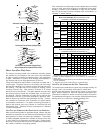
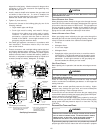
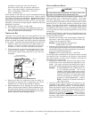
GAS VALVE
This unit is equipped with a 24 volt gas valve controlled during
furnace operation by the integrated control module. As shipped,
the valve is configured for natural gas. The valve is field convertible
for use with propane gas by replacing the regulator spring with a
propane gas spring from an appropriate manufacturer’s propane
gas conversion kit. Taps for measuring the gas supply pressure
and manifold pressure are provided on the valve.
The gas valve has a manual ON/OFF control located on the valve
itself. This control may be set only to the “ON” or “OFF” position.
Refer to the lighting instructions label or Section XIV, Startup Pro-
cedure & Adjustment for use of this control during start up and shut
down periods.
GAS PIPING CONNECTIONS
GENERAL
CAUTION
T
O AVOID POSSIBLE UNSATISFACTORY OPERATION OR EQUIPMENT DAMAGE
DUE TO UNDERFIRING OF EQUIPMENT, USE THE PROPER SIZE OF
NATURAL/PROPANE GAS PIPING NEEDED WHEN RUNNING PIPE FROM THE
METER/TANK TO THE FURNACE.
When sizing a trunk line, be sure to include all appliances which
will operate simultaneously when sizing a trunk line.
The gas piping supplying the furnace must be properly sized based
on the gas flow required, specific gravity of the gas, and length of
the run. The gas line installation must comply with local codes, or
in their absence, with the latest edition of the National Fuel Gas
Code, NFPA 54/ANSI Z223.1.
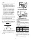
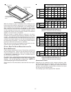
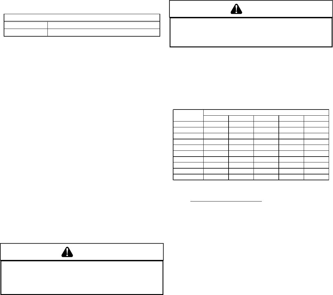
Natural Gas Capacity of Pipe
In Cubic Feet of Gas Per Hour (CFH)
Length of Nominal Black Pipe Size
Pipe in Feet 1/2" 3/4" 1" 1 1/4" 1 1/2"
10 132 278 520 1050 1600
20 92 190 350 730 1100
30 73 152 285 590 980
40 63 130 245 500 760
50 56 115 215 440 670
60 50 105 195 400 610
70 46 96 180 370 560
80 43 90 170 350 530
90 40 84 160 320 490
100 38 79 150 305 460
(Pressure 0.5 psig or less and pressure drop of 0.3" W.C.; Based on
0.60 Specific Gravity Gas)
CFH =
BTUH Furnace Input
Heating Value of Gas (BTU/Cubic Foot)
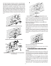
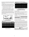
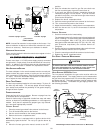
To connect the furnace to the building’s gas piping, the installer
must supply a ground joint union, drip leg, manual shutoff valve,
and line and fittings to connect to gas valve. In some cases, the
installer may also need to supply a transition piece from 1/2" pipe
to a larger pipe size.
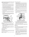
The following stipulations apply when connecting gas piping. Re-
fer to Gas Piping Connections figure for typical gas line connec-
tions to the furnace.
• Use black iron or steel pipe and fittings for building piping.
Where possible, use new pipe that is properly chamfered,
reamed, and free of burrs and chips. If old pipe is used, be
sure it is clean and free of rust, scale, burrs, chips, and old
pipe joint compound.
• Use pipe joint compound on male threads ONLY. Always
use pipe joint compound (pipe dope) that is APPROVED
FOR ALL GASSES. DO NOT apply compound to the first two
threads.
• Use ground joint unions.
• Install a drip leg to trap dirt and moisture before it can enter
the gas valve. The drip leg must be a minimum of three
inches long.
• Install a 1/8" NPT pipe plug fitting, accessible for test gage
connection, immediately upstream of the gas supply
connection to the furnace.
• Always use a back-up wrench when making the connection
to the gas valve to keep it from turning. The orientation of
the gas valve on the manifold must be maintained as