


20
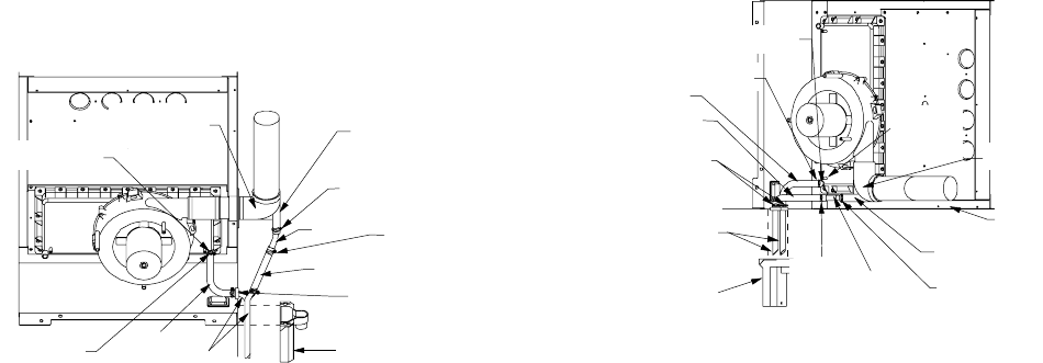
“right-side only” drain hoses to be connected as follows. Refer to
Section IX, Vent/Flue Pipe and Combustion Air Pipe for details on
alternate vent/flue pipe connection.
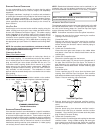
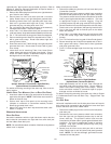
1. Remove the rubber plug from the front cover right-side drain
port. Save for use in step 3.
2. Secure Hose A to front cover drain port with a red hose
clamp. Route hose to rear right side panel grommet hole.
3. Remove grommet from front right-side panel drain hole.
Seal hole in grommet with large end of plug. Reinstall
grommet and plug into side panel drain hole.
4. Cut 1/4 inch from the end of the drain port on the externally
mounted rubber elbow. Discard cut portion.
5. Insert Tube 1 into rubber elbow drain port and secure with
a red hose clamp. Angle tube outward toward front of furnace.
6. Cut 17 7/8 inches from the long end of Hose B and discard.
7. Secure remaining end of Hose B to exposed end of Tube 1
with a green hose clamp. Route hose toward right side
panel grommet holes.
8. Insert short end of one Tube 2 through rear right side panel
grommet drain hole. Secure tube to Hose A with a green
hose clamp.
9. Insert short end of remaining Tube 2 into Hose B from
rubber elbow and secure with green hose clamp. Ensure
hoses and tubes maintain a downward slope for proper
drainage and are not kinked or binding.
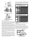
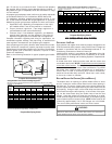
RUBBER ELBOW
(EXTERNALLY
MOUNTED)
TUBE 1
GREEN HOSE
CLAMPS
(3 PLACES)
HOSE B
TUBE(S) 2
DRAIN TRAP
SIDE PANEL
GROMMET
HOLES
HOSE A
FRONT COVER
DRAIN PORT
RUBBER
ELBOW
DRAIN PORT
RED HOSE
CLAMP
RED HOSE CLAMP
Upright “Alternate” Connections - Right Side Only
(Upflow Shown, Counterflow Similar)
For details concerning mounting of the drain trap, refer to the fol-
lowing section.
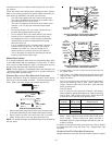
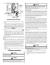
UPRIGHT DRAIN TRAP MOUNTING (LEFT OR RIGHT SIDE PANEL)
1. Insert drain tubes into drain trap and position the drain trap
against the side panel. NOTE: Drain tubes must reach the
bottom of the drain trap.
2. Secure drain trap to side panel at the mounting holes
(dimples or crosshairs on counterflow models) located
below the grommet drain holes.
3. Attach PVC drain line to drain trap outlet with either a 90°
elbow or coupling.
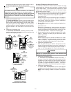
HORIZONTAL INSTALLATIONS
RIGHT SIDE DOWN
Horizontal installations with the right side down require that the
drain hoses be connected to the right side front cover drain port
and the rubber elbow drain port.
NOTE: On counterflow models, relocation of the front cover pressure
switch hose is required.
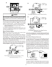
Make connections as follows:
1. Remove the rubber plug from the coil front cover drain port.
Counterflow furnaces
Relocate the front cover pressure switch hose connection
from the left side pressure tap to the right (down) side tap.
The pressure switch hose must be connected to the down
side to guard against blocked drain conditions. Cut hose
to appropriate length to minimize sagging. Plug left
(unused) pressure tap with plug removed from right side.
2. Secure Hose A to front cover drain tap with a red hose clamp.
Route hose to rear right (down) side panel grommet holes.
3. Cut 1/4 inch from the end of the drain port on the rubber
elbow and discard.
4. Insert Tube 1 into rubber elbow drain port and secure with
a red hose clamp. Angle tube outward toward front of
furnace.
5. Cut 17 3/4 inches from the long end of Hose B and discard.
6. Secure remaining end of Hose B to exposed end of Tube 1
with a green hose clamp. Route hose to front right down
side panel grommet holes.
7. Cut 5 1/2 inches straight length from the long end of each
Tube 2.
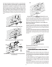
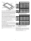
HOSE A
HOSE B
SIDE PANEL
GROMMET
HOLES
GREEN
HOSE
CLAMP
(3 PLACES)
TUBE 1
RUBBER
ELBOW
RIGHT
SIDE
PANEL
DRAIN TRAP
TUBES 2
RUBBER ELBOW
DRAIN PORT
FRONT COVER
DRAIN PORT
FRONT
COVER
PRESSURE
TAP
RED HOSE
CLAMP
RED HOSE
CLAMP
Horizontal Connections - Right Side Down
(Upflow Shown, Counterflow Similar)
8. Insert approximately one inch of each Tube 2 through the
right down side panel grommet holes. Secure tubes to
Hose A and Hose B using green hose clamps. Ensure
hoses and tubes maintain a downward slope for proper
drainage and are not kinked or bound.
For details concerning mounting of the drain trap, refer to Section
X, Condensate Drain Lines and Drain Trap - Upright Drain Trap
Mounting.
LEFT SIDE DOWN
Horizontal installations with the left side panel down will require
drain hoses to be connected to the left side front cover drain port
and the side drain port on the rubber elbow.
1. Remove the rubber plug from the coil front cover left (down)
side drain port.
2. Relocate the front cover pressure switch hose connection
from the right side (as shipped) pressure tap to the left
(down) side tap. The pressure switch hose must be
connected to the down side to guard against blocked drain
conditions. Cut hose to appropriate length to minimize
sagging. Plug right (unused) pressure tap with plug
removed from left side.
3. Secure Hose A to front cover drain port with a red hose
clamp. Route hose to rear left (down) side panel grommet
holes. NOTE: For left side drainage, grommets must be
relocated to left side panel.