


21
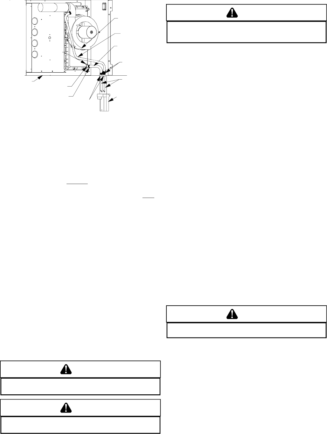
LEFT SIDE
PANEL
FRONT COVER
DRAIN PORT
SIDE PANEL
GROMMET
HOLES
DRAIN TRAP
TUBE(S) 2
GREEN HOSE
CLAMPS
(3 PLACES)
HOSE A
HOSE B
INDUCED
DRAFT BLOWER
DRAIN PORT
FRONT
COVER
PRESSURE
TAP
RED HOSE CLAMP
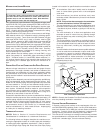
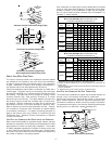
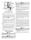
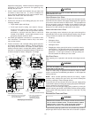
Horizontal Connections - Left Side Down
(Upflow Shown, Counterflow Similar)
4. Remove the rubber cap from the side drain port on the rubber
elbow.
5. Secure the short end of Hose B to rubber elbow side drain
port using a green hose clamp. NOTE: For left side drainage,
route hose to far left (down) side panel grommet holes.
NOTE: Horizontal left side connections (when using new
side port drain elbow)
does not require connecting a hose
to the induced draft blower housing.
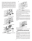
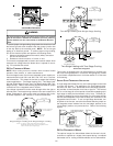
6. Cut 5 1/2 inches straight length from the long end of each
Tube 2.
7. Insert approximately one inch of each Tube 2 through left
side panel grommet hole. Secure tubes to Hose A and
Hose B with a green hose clamps. NOTE: Tube must
reach bottom of trap. Ensure hoses and tubes maintain a
downward slope for proper drainage and that they are not
kinked or binding.
For details concerning mounting of the drain trap, refer to Section
X, Condensate Drain Lines and Drain Trap - Upright Drain Trap
Mounting.
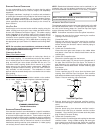
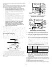
HORIZONTAL DRAIN TRAP MOUNTING (LEFT OR RIGHT SIDE PANEL)
1. Position the drain trap against side panel with drain tubes
inserted into trap. Note that the trap may be orientated with
the outlet facing either the furnace’s top cover or base pan.
2. Secure drain trap to side panel at the dimples or crosshairs
located on either side of the grommet drain holes.
3. Confirm that tubes reach bottom of drain trap and that all
hoses maintain a downward slope and are not kinked or
binding.
4. Attach PVC drain line to drain trap outlet with either a 90°
elbow or coupling.
XI. ELECTRICAL CONNECTIONSXI. ELECTRICAL CONNECTIONS
XI. ELECTRICAL CONNECTIONSXI. ELECTRICAL CONNECTIONS
XI. ELECTRICAL CONNECTIONS
WARNING
T
O AVOID THE RISK OF ELECTRICAL SHOCK, WIRING TO THE UNIT MUST BE
POLARIZED AND GROUNDED.
WARNING
T
O AVOID INJURY, ELECTRICAL SHOCK OR DEATH, DISCONNECT ELECTRICAL
POWER BEFORE SERVICING OR CHANGING ANY ELECTRICAL WIRING.
CAUTION
L
ABEL ALL WIRES PRIOR TO DISCONNECTION WHEN SERVICING CONTROLS.
W
IRING ERRORS CAN CAUSE IMPROPER AND DANGEROUS OPERATION.
V
ERIFY PROPER OPERATION AFTER SERVICING.
WIRING HARNESS
The wiring harness is an integral part of this furnace. Field alter-
ation to comply with electrical codes should not be required. Wires
are color and number coded for identification purposes. Refer to
the wiring diagram for wire routings. If any of the original wire as
supplied with the furnace must be replaced, it must be replaced
with wiring material having a temperature rating of at least 105°C.
Any replacement wiring must be copper conductor.
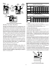
115 VOLT LINE CONNECTIONS
Before proceeding with electrical connections, ensure that the sup-
ply voltage, frequency, and phase correspond to that specified on
the unit rating plate. Power supply to the furnace must be N.E.C.
Class 1, and must comply with all applicable codes. The furnace
must be electrically grounded in accordance with local codes or, in
their absence, with the latest edition of The National Electric Code,
ANSI NFPA 70 and/or The Canadian Electric Code CSA C22.1.
Use a separate fused branch electrical circuit containing properly
sized wire, and fuse or circuit breaker. The fuse or circuit breaker
must be sized in accordance with the maximum overcurrent pro-
tection specified on the unit rating plate. An electrical disconnect
must be provided at the furnace location.
NOTE: Line polarity must be observed when making field
connections.
Connect hot, neutral, and ground wires as shown in the wiring
diagram located on the unit’s blower door. For direct vent applica-
tions, the cabinet opening to the junction box must be sealed air
tight using either an UL approved bushing such as Heyco Liquid
Tight or by applying non-reactive UL approved sealant to bushing.
Line polarity must be observed when making field connections.
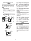
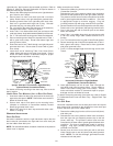
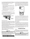
Line voltage connections can be made through either the right or
left side panel. The furnace is shipped configured for a left side
(right side for counterflows) electrical connection with the junction
box located inside the burner compartment. To make electrical
connections through the opposite side of the furnace, the junction
box must be relocated to the other side of the burner compartment
prior to making electrical connections. To relocate the junction box,
follow the steps shown below.
CAUTION
E
DGES OF SHEET METAL HOLES MAY BE SHARP.
U
SE GLOVES A PRECAUTION
WHEN REMOVING HOLE PLUGS.
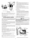
1. Remove the burner compartment door.
2. Remove and save the two screws securing the junction box
to the side panel.
3. Relocate junction box and associated plugs and grommets
to opposite side panel. Secure with screws removed in
step 2.