


5
I. COI. CO
I. COI. CO
I. CO
MPOMPO
MPOMPO
MPO
NENT IDNENT ID
NENT IDNENT ID
NENT ID
ENTIFIENTIFI
ENTIFIENTIFI
ENTIFI
CC
CC
C
AA
AA
A
TITI
TITI
TI
OO
OO
O
NN
NN
N
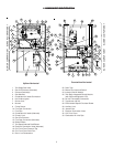
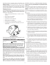
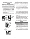
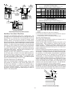
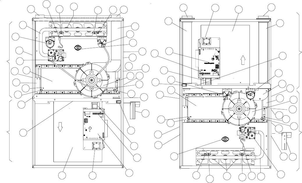
1 Two-Stage Gas Valve
2 Gas Line Entrance (Alternate)
3 Pressure Switch(es)
4 Gas Manifold
5 Combustion Air Intake Connection
6 Hot Surface Igniter
7 Rollout Limit
8 Burners
9 Flame Sensor
10 Flue Pipe Connection
11 Flue Pipe
12 Combustion Air Intake (Alternate)
13 Primary Limit
14 Gas Line Entrance
15 Flue Pipe Connection (Alternate)
16 Rubber Elbow
17 Two-Speed Induced Draft Blower
18 Electrical Connection Inlets (Alternate)
19 Coil Front Cover Pressure Tap
20 Coil Front Cover Drain Port
21 Drain Line Penetrations
22 Drain Trap
23 Blower Door Interlock Switch
24 Inductor (Not All Models)
25 Two-Stage Integrated Control Module
(with fuse and diagnostic LED)
26 24 Volt Thermostat Connections
27 Transformer (40 VA)
28 ECM Variable Speed Circulator Blower
29 Auxiliary Limit
30 Junction Box
31 Electrical Connection Inlets
32 Coil Front Cover
33 Combustion Air Inlet Pipe
Upflow/Horizontal
Counterflow/Horizontal
BLOWER COMPARTMENT BURNER COMPARTMENT
1
2
3
4
5
6
7
8
7
9 10
11
3
12
13
14
15
16
17
19
20
21
24
26
23
30
25
27
28
29
22
21
20
19
32
18
31
123
45
6
9
8
7
1211
10
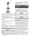
CFM
USC
WR
DEHUM
CUT FOR
1
2
3
87 4321
87 4321
Intell-Ignition
TSTAT
S4
S3
OFF
ON
S1
SINGLE
TWO
ON
OFF
*
*
*
*
**
*
*
*
BURNER COMPARTMENT BLOWER COMPARTMENT
1
9
7
8
7
4
6
13
14
22
21
20
19
32
3
25
24
26
33
5
27
28
10
29
3
16
15
17
12
19
20
21
2
11
18
31
30
23