


30
Installation’s seconds per cubic foot: 34 sec/ ft
3
Conversion Factor (hours to seconds): 3600 sec/hr
Input = (Htg. value x 3600) ÷ seconds per cubic foot
Input = (1,000 BTU/ft
3
x 3600 sec/hr) ÷ 34 sec/ ft
3
Input = 106,000 BTU/hr
Minor changes to the input rate may be accomplished through
manifold pressure adjustments at the gas valve. Refer to Section
XIV, Startup Procedure and Adjustment - Gas Manifold Pressure
Measurement and Adjustment for details. NOTE: The final mani-
fold pressure cannot vary by more than ± 0.3” w.c. from the speci-
fied setting. Consult your local gas supplier if additional input rate
adjustment is required.
5. Repeat steps 2 through 4 on high stage.
6. Turn ON gas to and relight all other appliances turned off in
step 1. Be certain that all appliances are functioning properly
and that all pilot burners are operating.
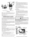
TEMPERATURE RISE
Temperature rise must be within the range specified on the unit
rating plate. An incorrect temperature rise may result in condens-
ing in or overheating of the heat exchanger. An airflow and tem-
perature rise table is provided in the Product Data Book applicable
to your model*. Determine and adjust temperature rise as follows:
1. Operate furnace with burners firing for approximately ten
minutes. Ensure all registers are open and all duct
dampers are in their final (fully or partially open) position.
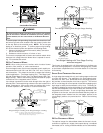
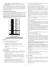
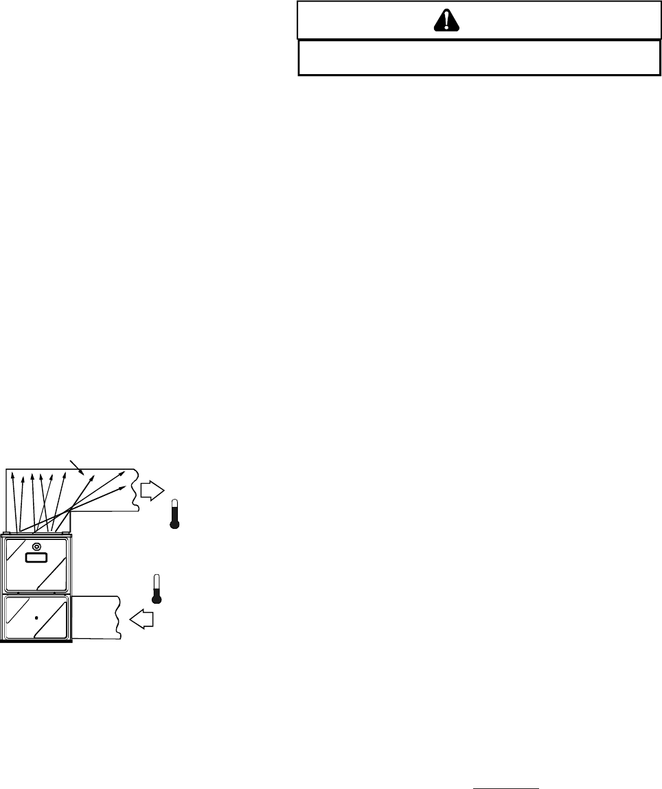
2. Place thermometers in the return and supply ducts as close
to the furnace as possible. Thermometers must not be
influenced by radiant heat by being able to “see” the heat
exchanger.
RISE =
SUPPLY
AIR
RETURN
AIR
HEAT EXCHANGER
RADIATION "LINE OF SIGHT"
T
RETURN
T
SUPPLY
T
SUPPLY
-
T
RETURN
Temperature Rise Measurement
3. Subtract the return air temperature from the supply air
temperature to determine the air temperature rise. Allow
adequate time for thermometer readings to stabilize.
4. Adjust temperature rise by adjusting the circulator blower
speed. Increase blower speed to reduce temperature rise.
Decrease blower speed to increase temperature rise. Refer
to Section XIV, Startup Procedure and Adjustment -Circulator
Blower Speeds for speed changing details.
CIRCULATOR BLOWER SPEEDS
WARNING
T
O AVOID PERSONAL INJURY OR DEATH DUE TO ELECTRICAL SHOCK, TURN
OFF POWER TO THE FURNACE BEFORE CHANGING SPEED TAPS.
This furnace is equipped with a multi-speed circulator blower. This
blower provides ease in adjusting blower speeds. The Product
Data Book applicable to your model* provides an airflow table,
showing the relationship between airflow (CFM) and external static
pressure (E.S.P.), for the proper selection of heating and cooling
speeds. The heating blower speed is shipped set at “B”, and the
cooling blower speed is set at “D”. These blower speeds should
be adjusted by the installer to match the installation requirements
so as to provide the correct heating temperature rise and correct
cooling CFM.
Use the CFM LED (green), adjacent to the integrated control mod-
ule fuse to verify airflow quantity. The green CFM LED blinks once
for each 100 CFM of airflow.
1. Determine the tonnage of the cooling system installed with
the furnace. If the cooling capacity is in BTU/hr divide it by
12,000 to convert capacity to TONs.
Example: Cooling Capacity of 30,000 BTU/hr.
30,000/12,000 = 2.5 Tons
2. Determine the proper air flow for the cooling system. Most
cooling systems are designed to work with air flows between
350 and 450 CFM per ton. Most manufacturers recommend
an air flow of about 400 CFM per ton.
Example: 2.5 tons X 400 CFM per ton = 1000 CFM
The cooling system manufacturer’s instructions must be checked
for required air flow. Any electronic air cleaners or other devices
may require specific air flows, consult installation instructions of
those devices for requirements.
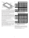
3. Knowing the furnace model, locate the high stage cooling
air flow charts in the Product Data Book applicable to your
model*. Look up the cooling air flow determined in step 2
and find the required cooling speed and adjustment setting.
Example: A *MV90704BXA furnace installed with a 2.5
ton air conditioning system. The air flow
needed is 1000 CFM. Looking at the cooling
speed chart for *MV90704BXA, find the air flow
closest to 1000 CFM. A cooling airflow of 990
CFM can be attained by setting the cooling
speed to “C” and the adjustment to “-” (minus).
NOTE: Continuous Fan Speed will be 56% of
high stage cooling.
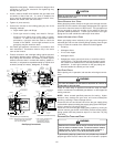
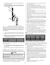
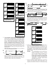
4. Locate the blower speed selection DIP switches on the
integrated control module. Select the desired “cooling”
speed tap by positioning switches 1 and 2 appropriately.
Select the desired “adjust” tap by positioning switches 3
and 4 appropriately. Refer to the following figure for switch
positions and their corresponding taps. Turn off power to
furnace for a minimum of
10 seconds, allowing motor to
reset and recognize new speed selection. Turn on power
to furnace. Verify CFM by counting the number of times the
green CFM LED blinks.
*NOTE: Please contact your distributor or our website for the applicable product data book referred to in this manual.