


16
12345678
45,000 2 7168656259565350
2 4946434037343128
3 7168656259565350
90,000
3 7168656259565350
115,000
3 4946434037343128
12345678
2 6158555249464340
3 7168656259565350
2 6158555249464340
3 7168656259565350
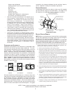
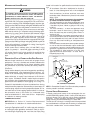
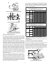
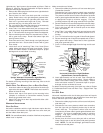
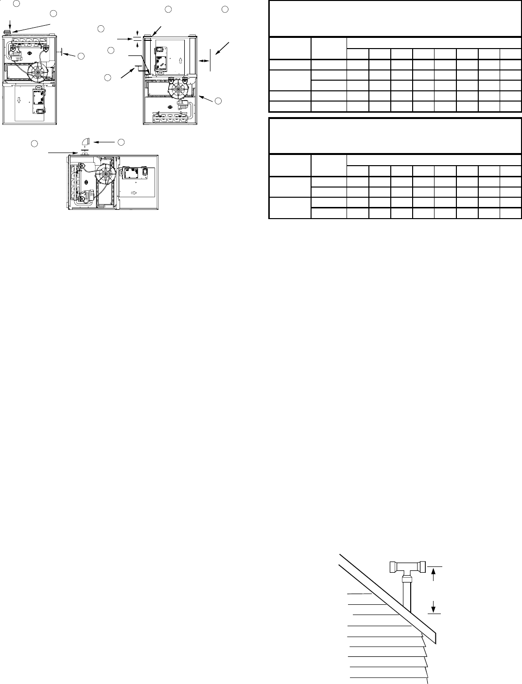
UPFLOW
Non-Direct Vent (Single Pipe)
Maximum Allowable Length of Vent/Flue Pipe (ft)
(1)(2)
70,000
Number of Elbows
(3)
Pipe
(4)
(Inch)
Unit Input
70,000
90,000
COUNTERFLOW
Non-Direct Vent (Single Pipe)
Maximum Allowable Length of Vent/Flue Pipe (ft)
(1)(2)
Unit Input
Pipe
(4)
(Inch)
Number of Elbows
(3)
(1) One 90° elbow should be secured to the combustion air intake con-
nection.
(2) Minimum vent length is five feet and one elbow/tee.
(3) Tee used in the vent/flue termination must be included when determin-
ing the number of elbows in the piping system.
(4) 3” diameter pipe can be used in place of 2” diameter pipe.
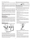
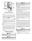
VENT/FLUE PIPE TERMINATIONS
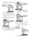
The vent/flue pipe may terminate vertically, as through a roof, or
horizontally, as through an outside wall.
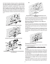
Vertical vent/flue pipe terminations should be as shown in the
following figure. Refer to Section IX, Vent/Flue Pipe and Com-
bustion Air Pipe - Termination Locations for details concerning
location restrictions. The penetration of the vent through the roof
must be sealed tight with proper flashing such as is used with a
plastic plumbing vent.
Horizontal vent/flue pipe terminations should be as shown in the
following figure. Refer to Section IX, Vent/Flue Pipe and Combus-
tion Air Pipe - Termination Locations for details concerning loca-
tion restrictions. A 2 3/8” diameter wall penetration is required for
2” diameter pipe while a 3 1/2” diameter hole is required for 3”
diameter pipe. To secure the pipe passing through the wall and
prohibit damage to piping connections, a coupling should be in-
stalled on either side of the wall and solvent cemented to a length
of pipe connecting the two couplings. The length of pipe should
be the wall thickness plus the depth of the socket fittings to be
installed on the inside and outside of the wall. The wall penetra-
tion should be sealed with silicone caulking material.
In a basement installation, the vent/flue pipe can be run between
joist spaces. If the vent pipe must go below a joist and then up
into the last joist space to penetrate the header, two 45° elbows
should be used to reach the header rather than two 90° elbows.
12 " Min To
Roof Or
Highest Anticipated
Snow Level
TEE
Vertical Termination (Single Pipe)
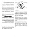
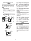
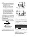
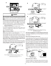
ADDITIONAL
PLUG FROM
DRAIN KIT
SECURE
TO CABINET
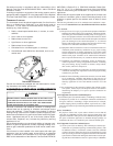
UPFLOW/HORIZONTAL SHOWN
(COUNTERFLOW SIMILAR)
REMOVE
3 SCREWS
REMOVE
4 SCREWS
REMOVE
4 SCREWS
REMOVE
AND
RELOCATE
.
REMOVE
AND
RELOCATE
REMOVE
AND CUT
REMOVE
UPFLOW
COUNTERFLOW
5
4
1
2
2
3
3
1
1
3
2" CLEARANCE
REQUIRED
(NON-DIRECT
VENT)
5
Alternate Combustion Air Intake Location
NON-DIRECT VENT (SINGLE PIPE) PIPING
Non-direct vent installations require only a vent/flue pipe. The
vent pipe can be run horizontally with an exit through the side of
the building or run vertically with an exit through the roof of the
building. The vent can also be run through an existing unused
chimney; however, it must extend a minimum of 12 inches above
the top of the chimney. The space between the vent pipe and the
chimney must be closed with a weather-tight, corrosion-resistant
flashing. For details concerning connection of the vent/flue pipe
to the furnace, refer to Section IX, Vent/Flue Pipe and Combustion
Air - Standard Furnace Connections or Alternate Furnace Con-
nections for specific details. Refer to the following Non-Direct
Vent (Single Pipe) Piping - Vent/Flue Pipe Terminations for spe-
cific details on termination construction.
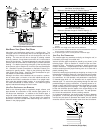
Although non-direct vent installations do not require a combus-
tion air intake pipe, a minimum of one 90° elbow should be at-
tached to the furnace’s combustion air intake if: an upright instal-
lation uses the standard intake location, or a horizontal installa-
tion uses the alternate air intake location. This elbow will guard
against inadvertent blockage of the air intake.
VENT/FLUE PIPE LENGTHS AND DIAMETERS
Refer to the following table for applicable length, elbows, and
pipe diameter for construction of the vent/flue pipe system of a
non-direct vent installation. In addition to the vent/flue pipe, a
single 90° elbow should be secured to the combustion air intake
to prevent inadvertent blockage. The tee used in the vent/flue
termination must be included when determining the number of
elbows in the piping system.