


14
STANDARD F URNACE C ONNECTIONS
It is the responsibility of the installer to ensure that the piping
connections to the furnace are secure, airtight, and adequately
supported.
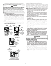
As shipped, attachment “couplings” for vent/flue and combustion
air intake pipe connections are provided on the furnace’s top cover
(upflow) or basepan (counterflow). To use the standard connec-
tions, field supplied vent/flue pipe and combustion air intake pipe
(when applicable) should be secured directly to the furnace at
these locations.
VENT/FLUE PIPE
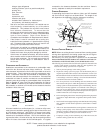
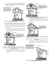
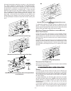
Vent/flue pipe can be secured to the vent/flue coupling using the
rubber coupling and worm gear hose clamps provided with this
furnace (see “Standard Connections” figure). The rubber coupling
allows separation of the vent/flue pipe from the furnace during
servicing. NOTE: Do not use other commercially available “no hub
connectors” due to possible material conflicts. The vent/flue pipe
can also be secured using a PVC or ABS elbow or coupling using
the appropriate glue (see Section IX, Materials and Joining Meth-
ods.
NOTE: For non-direct vent installations, a minimum of one 90°
elbow should be installed on the combustion air intake coupling
to guard against inadvertent blockage.
COMBUSTION AIR PIPE
DIRECT VENT INSTALLATIONS
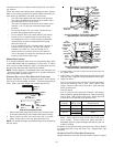
On upflow units secure the combustion air intake pipe directly to
the air intake coupling. On counterflow units secure the combus-
tion air intake pipe to the air intake coupling using the rubber cou-
pling and worm gear hose clamps provided with the unit. The
counterflow rubber coupling allows service removal of air intake
piping internal to the furnace blower compartment. NOTE: Be-
cause of probable material conflicts, do not use other commer-
cially available “no hub connectors”. The combustion air intake
pipe can also be secured directly to the counterflow unit air intake
pipe coupling.
NON-DIRECT V ENT I NSTALLATIONS
A minimum of one 90° elbow should be installed on the combus-
tion air intake “coupling” to guard against inadvertent blockage.
RUBBER
CO UPLING
WITH WORM
GEAR CLAMPS
RUBBER
COUPLINGS
WITH WORM
GEAR CLAMPS
COMBUSTION
AIR PIPE
(DIRECT VENT ONLY)
COMBUSTION
AIR PIPE
(DIRECT VENT ONLY)
VENT/FLUE
PIPE
VENT/FLUE
PIPE
90 PVC
ELBOW
(NON-DIRECT VENT)
90 PVC
ELBOW
(NON-DIRECT VENT)
STANDARD CONNECTIONS
OR
OR
UPFLOW COUNTERFLOW
Standard Connections
ALTERNATE F URNACE C ONNECTIONS
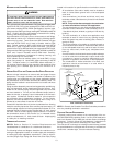
If the standard locations are undesirable for a specific installation,
alternate side panel locations are available for both combustion
air inlet and vent/flue pipe connections. These locations may be of
particular benefit to upright upflow installations requiring additional
access to an A coil, or to upright counterflow installations requiring
additional access to a filter or electronic air cleaner, or to horizontal
installations desiring vent/flue (and combustion air intake) piping
run vertically from the side of the cabinet.
NOTE: Standard and alternate locations can be combined (i.e., an
installation may use the standard combustion air intake location
but use the alternate vent/flue location or vice versa), if needed.
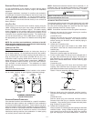
WARNING
E
DGES OF SHEET METAL HOLES MAY BE SHARP.
U
SE GLOVES AS A PRE-
CAUTION WHEN REMOVING HOLE PLUGS.
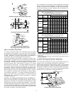
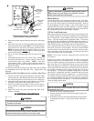
ALTERNATE VENT/FLUE LOCATION
The alternate vent/flue location is the large hole directly in line with
the induced draft blower outlet. To use the alternate vent/flue loca-
tion refer to the following steps, the “Vent/Flue Pipe Cuts” figure,
and the “Alternate Vent/Flue Location” figure.
NOTE: Counterflow instructions follow the upflow instructions.
1. Remove and save the four screws securing the vent/flue
coupling to the furnace top panel.
Counterflow units.
Remove and save the four screws securing the vent/flue
coupling to the furnace basepan. Also remove the three
screws securing the furnace’s internal vent/flue piping to
the blower deck.
2. Upflow and Counterflow units.
Loosen the worm gear hose clamps on the rubber elbow
and detach it from both the induced draft blower and the
vent/flue pipe.
3. Upflow and Counterflow units.
Remove the vent/flue pipe from the furnace.
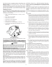
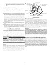
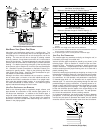
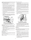
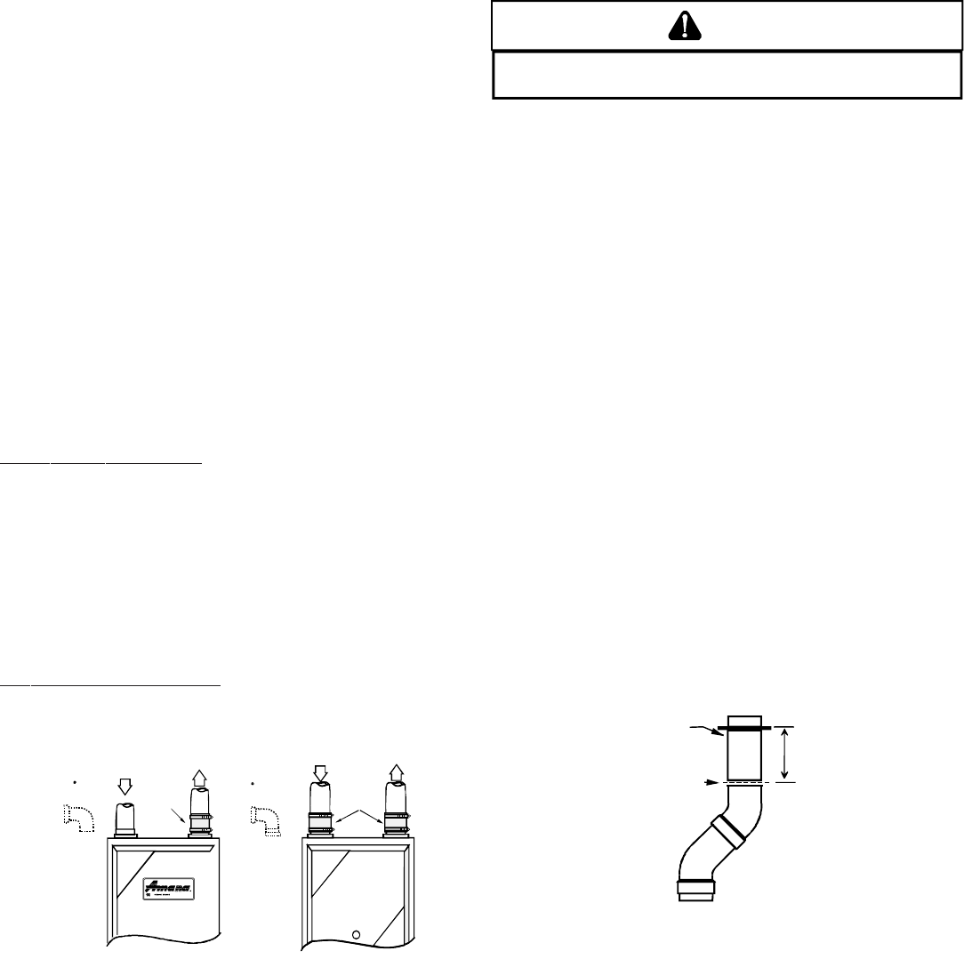
4. Cut the vent/flue pipe 3.75 inches from the flanged end of
the pipe. See Vent/Flue Pipe Cuts figure. The section of
pipe attached to the coupling will reach through the side
panel to the induced draft blower. Discard remaining pipe
and elbows.
Counterflow units.
Cut the vent/flue pipe 3.75 inches from the blower deck
coupling. See Vent/Flue Pipe Cuts figure. Save vent/flue
pipe attached to blower deck coupling for use in the alternate
location. Discard remaining pipe and elbows.
FLANGE
CUT
HERE
3.75"
Vent/Flue Pipe Cuts
5. Remove plastic plug from alternate vent/flue location.
Relocate and install plug in standard vent/flue location (top
cover).
Counterflow units.
Remove plastic plug from alternate vent/flue location.
Relocate and install plug in standard vent/flue location
(basepan). Plug remaining hole in blower deck with plastic
plug included in the drain kit bag.
6. Upflow and Counterflow units.
Insert cut section of vent/flue pipe and coupling into alternate
vent/flue location. Using a rubber coupling and worm gear
hose clamps from the drain kit bag, attach the vent/flue
pipe and coupling to the induced draft blower. Secure the