


25
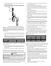
CAUTION
E
DGES OF SHEET METAL HOLES MAY BE SHARP.
U
SE GLOVES A PRECAUTION
WHEN REMOVING HOLE PLUGS.
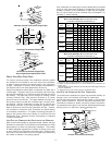
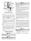
DIRECT/STANDARD INLET PIPING
When gas piping enters directly to the gas valve through the stan-
dard inlet hole, the installer must supply straight pipe with a ground
joint union to reach the exterior of the furnace. The rigid pipe must
be long enough to reach the outside of the cabinet to seal the
grommet cabinet penetration. A semi-rigid connector to the gas
piping can be used outside the cabinet per local codes.
INDIRECT/ALTERNATE INLET PIPING
When gas piping enters indirectly to the gas valve through the
alternate gas inlet hole the following fittings (starting from the gas
valve) to reach the outside of the cabinet must be supplied:
• Coupling.
• 90 degree elbow.
• 2 inch close nipple.
• 90 degree elbow.
• Straight pipe, with a ground joint union, to reach the exterior
of the furnace. The rigid pipe must be long enough to reach
the outside of the cabinet so as to seal the grommet cabinet
penetration. A semi-rigid connector to the gas piping can
be used outside the cabinet per local codes.
GAS PIPING CHECKS
Before placing unit in operation, leak test the unit and gas connec-
tions.
WARNING
T
O AVOID THE POSSIBILITY OF EXPLOSION OR FIRE, NEVER USE A MATCH OR
OPEN FLAME TO TEST FOR LEAKS.
Check for leaks using an approved chloride-free soap and water
solution, an electronic combustible gas detector, or other approved
testing methods.
NOTE: Never exceed specified pressures for testing. Higher
pressure may damage the gas valve and cause subsequent
overfiring, resulting in heat exchanger failure.
Disconnect this unit and shutoff valve from the gas supply piping
system before pressure testing the supply piping system with pres-
sures in excess of 1/2 psig (3.48 kPa).
Isolate this unit from the gas supply piping system by closing its
external manual gas shutoff valve before pressure testing supply
piping system with test pressures equal to or less than 1/2 psig
(3.48 kPa).
PROPANE GAS TANKS AND PIPING
WARNING
P
ROPANE GAS IS HEAVIER THAN AIR AND ANY LEAKING GAS CAN SETTLE IN
ANY LOW AREAS OR CONFINED SPACES.
T
O PREVENT PROPERTY DAMAGE,
PERSONAL INJURY, OR DEATH DUE TO FIRE OR EXPLOSION CAUSED BY A
PROPANE GAS LEAK, INSTALL A GAS DETECTION WARNING DEVICE.
A gas detecting warning system is the only reliable way to detect a
propane gas leak. Rust can reduce the level of odorant in propane
shipped from the factory. Maximum torque for the gas valve
connection is 375 in-lbs; excessive over-tightening may
damage the gas valve.
• Install a manual shutoff valve between the gas meter and
unit within six feet of the unit. If a union is installed, the
union must be downstream of the manual shutoff valve,
between the shutoff valve and the furnace.
• Tighten all joints securely.
• Connect the furnace to the building piping by one of the
following methods:
– Rigid metallic pipe and fittings.
– Semi-rigid metallic tubing and metallic fittings.
Aluminum alloy tubing must not be used in exterior
locations. In order to seal the grommet cabinet
penetration, rigid pipe must be used to reach the
outside of the cabinet. A semi-rigid connector to the
gas piping may be used from there.
• Use listed gas appliance connectors in accordance with
their instructions. Connectors must be fully in the same
room as the furnace.
• Protect connectors and semirigid tubing against physical
and thermal damage when installed. Ensure aluminum-
alloy tubing and connectors are coated to protect against
external corrosion when in contact with masonry, plaster, or
insulation, or subjected to repeated wetting by liquids such
as water (except rain water), detergents, or sewage.
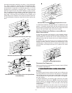
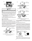
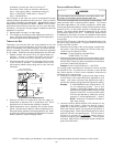
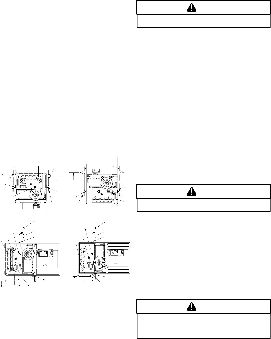
MANUAL
SHUT OFF VALVE
(UPSTREAM FROM
GROUND JOINT
PIPE UNION)
GROMMET
IN STANDARD
GAS LINE HOLE
A
LTERNATE
GAS L INE
LOCATION
PLUG IN
A
LTERNATE
GAS L INE
HOLE
HEIGHT REQUIRED
BY LOCAL CODE
GROUND JOINT
PIPE UNION
DRIP LEG
MANIFOLD
BURNERS
GAS VALVE
HORIZONTAL [UPFLOW MODEL]
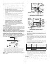
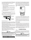
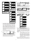
MANUAL SHUT-OFF VALVE
(UPSTREAM FROM GROUND
JOINT PIPE UNION)
DRIP LEG
GROMMET IN STANDARD
GAS LINE HOLE
DRAI N TRAP
ALTERNATE GAS
LINE LOC ATION
MANIFOLD
PLUG IN ALTERNATE
GAS LINE HOLE
GAS VALVE
GROUND JOINT
PIPE UNION
BURN ERS
GROMMET
IN STANDARD
GAS LINE HOLE
*
**
*
COUNTERFLOW
MANUAL
SHUT OFF VALVE
(UPSTREAM FRO M
GROUND JOINT
PIPE UNION )
ALTERNATE
GAS LINE
LOCATION
PLUG IN
ALTERNATE
GAS LINE
HOLE
HEIGHT REQUIRED
BY LOCAL CODE
GROUND JOINT
PIPE UNION
DRIP LEG
MANIFOLD
BURNERS
GAS VALVE
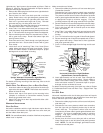
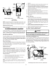
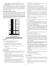
NOTES
:
1.
WHEN
GAS
LINE
IS
IN
THE
ALTERNATE
LOCATION
,
SWAP
THE
POSITION
OF
THE
PLUG
AND
GROMMET
.
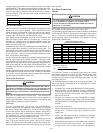
MANUAL SHUT-OFF VALVE
(UPSTREAM FROM GROUND
JOINT PIPE UNION)
DRIP LEG
GROMMET IN STANDARD
GAS LINE HOLE
DRAIN TRAP
ALTERNAT E
GAS LINE LOCATION
MANIFOLD
PLUG IN ALTERNATE
GAS LINE HOLE
BURNER S
GAS VALVE
HORIZONTAL[COUNTERFLOW]
UPFLOW
GROUND JOINT
PIPE UNION
2. DRIP LEG MAY TERMINATE WITH
A 1/2" X 1/8" PIPE PLUG TO
ACCOMMODATE LINE GAS
PRESSURE MEASUREMENT.
Gas Piping Connections