


12
AIR
DISCHARGE
AIR
DISCHARGE
AIR
DISCHARGE
Bottom
Return
Duct
Connection
Bottom
Return
Duct
Connection
Bottom
Return
Duct
Connection
Side
Return
Duct
Connection
Side
Return
Duct
Connection
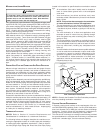
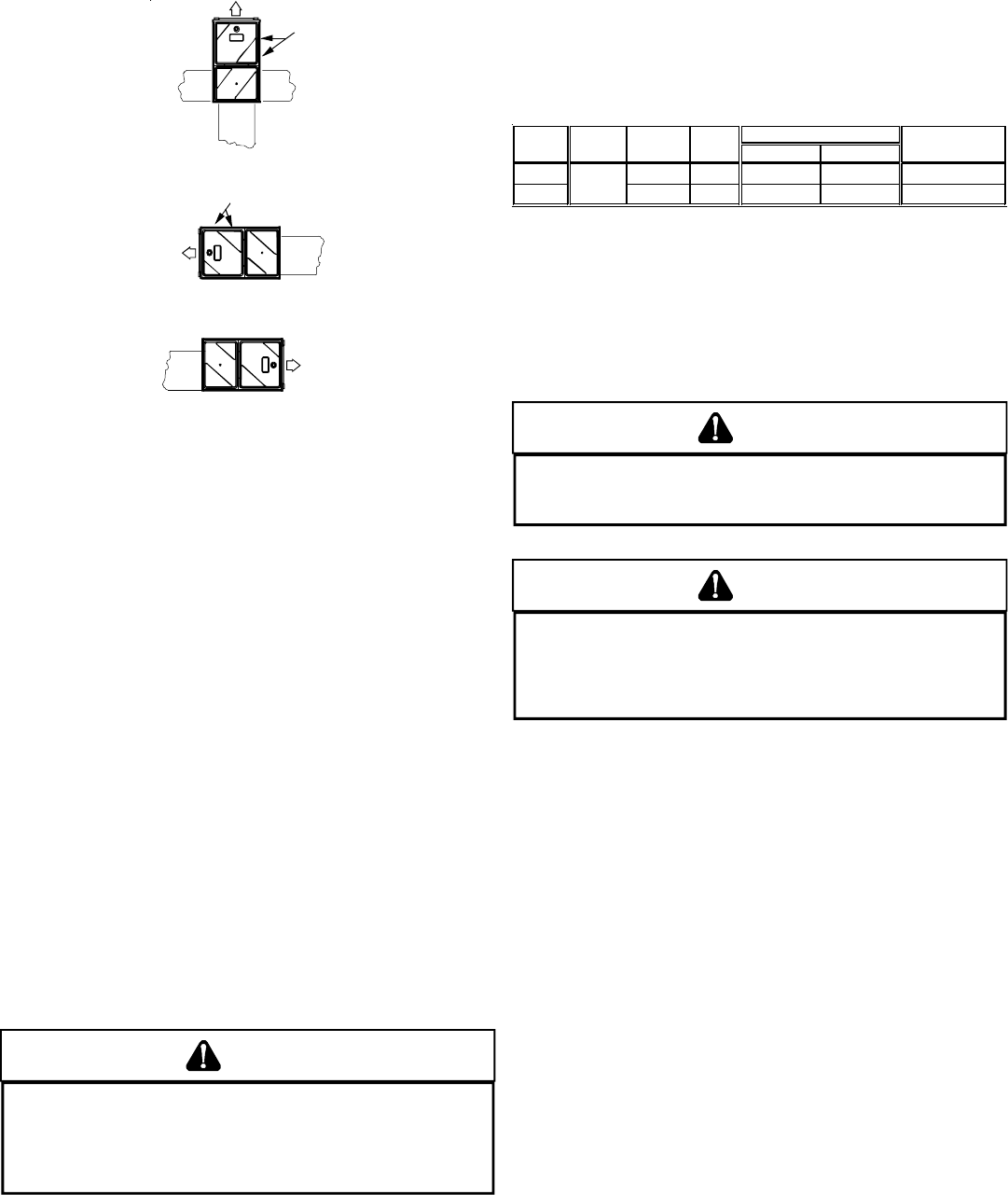
UPFLOW
UPRIGHT
UPFLOW HORIZONTAL
RIGHT AIR DISCHARGE
UPFLOW HORIZONTAL
LEFT AIR DISCHARGE
ALTERNATE FLUE AND
COMBUSTION AIR PIPE
LOCATIONS
ALTERNATE FLUE AND
COMBUSTION AIR PIPE
LOCATIONS
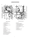
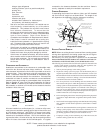
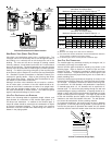
Recommended Installation Positions
NOTE: Alternate “vertical” piping connections can not be used when
an upflow furnace is installed with supply air discharging to the
right, or when a counterflow furnace is installed with supply air
discharging to the left. In either case, use the standard flue and
combustion air piping connections.
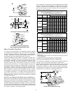
ALTERNATE E LECTRICAL AND G AS L INE C ONNECTIONS
This furnace has provisions allowing for electrical and gas line
connections through either side panel. In horizontal applications
the connections can be made either through the “top” or “bottom” of
the furnace.
DRAIN PAN
A drain pan must be provided if the furnace is installed above a
conditioned area. The drain pan must cover the entire area under
the furnace (and air conditioning coil if applicable).
FREEZE P ROTECTION
Refer to Section VI, Horizontal Applications and Conditions - Drain
Trap and Lines.
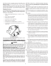
FURNACE S USPENSION
If the furnace is installed in a crawl space it must be suspended
from the floor joist or supported by a concrete pad. Never install the
furnace on the ground or allow it to be exposed to water. Refer to
Section IV, Location Requirements and Considerations - Furnace
Suspension for further details.
VIII. PRVIII. PR
VIII. PRVIII. PR
VIII. PR
OO
OO
O
PP
PP
P
ANE GAANE GA
ANE GAANE GA
ANE GA
S /HIS /HI
S /HIS /HI
S /HI
GH ALGH AL
GH ALGH AL
GH AL
TITUDTITUD
TITUDTITUD
TITUD
E INSTE INST
E INSTE INST
E INST
ALLALL
ALLALL
ALL
AA
AA
A
TITI
TITI
TI
OO
OO
O
NSNS
NSNS
NS
WARNING
P
OSSIBLE PROPERTY DAMAGE, PERSONAL INJURY OR DEATH MAY OCCUR IF
THE CORRECT CONVERSION KITS ARE NOT INSTALLED.
T
HE APPROPRIATE KITS
MUST BE APPLIED TO INSURE SAFE AND PROPER FURNACE OPERATION.
A
LL
CONVERSIONS MUST BE PERFORMED BY A QUALIFIED INSTALLER OR SERVICE
AGENCY.
This furnace is shipped from the factory configured for natural gas
at standard altitude. Propane gas installations require an orifice
change to compensate for the energy content difference between
natural and propane gas.
High altitude installations may require both a pressure switch and
an orifice change. These changes are necessary to compensate
for the natural reduction in the density of both the gas fuel and the
combustion air at higher altitude.
For installations above 7000 feet, please refer to your distributor
for required kit(s).
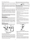
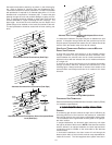
High Stage Low Stage
Natural None #43 3.5" w.c. 1.9" w.c. None
Propane
LPM-03B
#55 10.0" w.c. 6.0" w.c. None
Orifice
NOTE
:
I
n
C
ana
d
a, gas
f
urnaces are on
l
y cer
tifi
e
d
t
o
4500
f
ee
t
.
0-7000
Manifold Pressure Pressure
Switch Change
Gas Altitude Kit
Contact the distributor for a tabular listing of appropriate
manufacturer’s kits for propane gas and/or high altitude installa-
tions. The indicated kits must be used to insure safe and proper
furnace operation. All conversions must be performed by a quali-
fied installer, or service agency.
IX. VENT/FLUE PIPE & COMBUSTION AIR PIPEIX. VENT/FLUE PIPE & COMBUSTION AIR PIPE
IX. VENT/FLUE PIPE & COMBUSTION AIR PIPEIX. VENT/FLUE PIPE & COMBUSTION AIR PIPE
IX. VENT/FLUE PIPE & COMBUSTION AIR PIPE
GENERAL
WARNING
F
AILURE TO FOLLOW THESE INSTRUCTIONS CAN RESULT IN BODILY INJURY OR
DEATH.
C
AREFULLY READ AND FOLLOW ALL INSTRUCTIONS GIVEN IN THIS
SECTION.
WARNING
U
PON COMPLETION OF THE FURNACE INSTALLATION, CAREFULLY INSPECT THE
ENTIRE FLUE SYSTEM BOTH INSIDE AND OUTSIDE THE FURNACE TO ASSURE IT
IS PROPERLY SEALED.
L
EAKS IN THE FLUE SYSTEM CAN RESULT IN SERIOUS
PERSONAL INJURY OR DEATH DUE TO EXPOSURE TO FLUE PRODUCTS,
INCLUDING CARBON MONOXIDE.
A condensing gas furnace achieves its high level of efficiency by
extracting almost all of the heat from the products of combustion
and cooling them to the point where condensation takes place.
Because of the relatively low flue gas temperature and water con-
densation requirements, PVC pipe is used as venting material.
This furnace must not be connected to Type B, BW, or L vent or vent
connector, and must not be vented into any portion of a factory built
or masonry chimney except when used as a pathway for PVC as
described later in this section. Never common vent this appliance
with another appliance or use a vent which is used by a solid fuel
appliance. Do not use commercially available “no hub connec-
tors” other than those shipped with this product.
It is the responsibility of the installer to follow the manufacturers’
recommendations and to verify that all vent/flue piping and connec-
tors are compatible with furnace flue products. Additionally, it is the
responsibility of the installer to ensure that all piping and connec-
tions possess adequate structural integrity and support to prevent
flue pipe separation, shifting, or sagging during furnace operation.
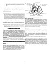
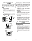
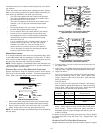
DUAL CERTIFICATION: NON-DIRECT/DIRECT V ENT
This furnace is dual certified and may be installed as a non-direct
vent (single pipe) or direct vent (dual pipe) appliance. A non-direct
vent installation requires only a vent/flue pipe, while a direct vent
installation requires both a vent/flue pipe and a combustion air
intake pipe. Refer to the appropriate section for details concerning
piping size, length, number of elbows, furnace connections, and
terminations.