


25
Please Do Not Return This Product To The Store. Contact your local Wayne-Dalton dealer. To find your local Wayne-Dalton dealer, refer to your
local yellow pages/business listings or go to the Find a Dealer section online at www.wayne-dalton.com
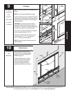
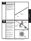
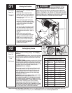
Tools Needed:
Tools Needed:
INSTALLATION
23
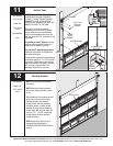
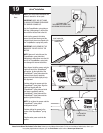
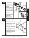
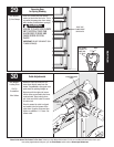
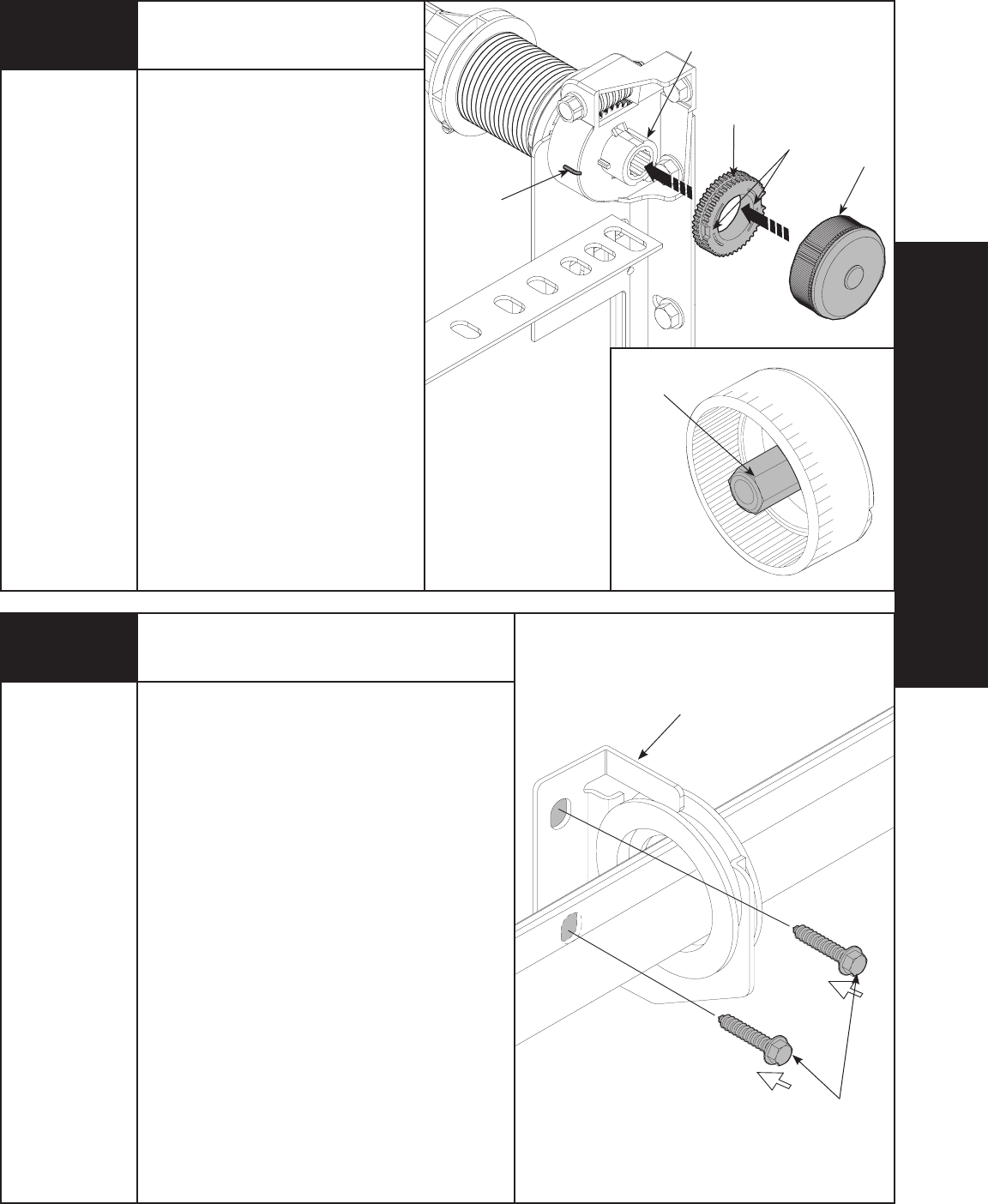
Counter Installation
Install the right side counter gear, with
the missing tooth toward the outside
and away from the end bracket. Press
the counter gear onto the end bracket
until snaps engage.
Select the right hand counter cover and
align the hex of the counter cam with
the end of the winding shaft. Also, align
the “0” on the counter cover with the
raised rib on the end bracket. Press the
counter cover against the counter gear
until it locks into place.
Repeat on left hand side for double
spring applications.
NOTE: No drive gear, counter gear or
counter cover is required on left hand
side for single spring applications. Only
an end bracket is needed.
IMPORTANT: AT THIS TIME DO NOT
WIND COUNTERBALANCE SPRINGS!
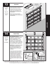
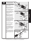
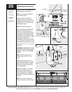
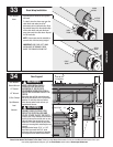
CENTER
BRACKET
ASSEMBLY
(2) 5/16” X 2” HEX
HEAD LAG SCREWS
Securing Center Bracket Bushing
24
HEX OF THE
COUNTER CAM
WINDING
SHAFT INSIDE
END BRACKET
MISSING
TOOTH
RAISED RIB
COUNTER
COVER
COUNTER
GEAR
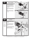
NOTE: If you are installing an idrive
®
opener on your
garage door, skip this step and continue with Step 25.
NOTE: If you are not installing an idrive
®
opener on
your garage door, you must install the center bracket
bushing assembly. Follow these instructions for
non-idrive
®
operated garage doors.
NOTE: If you are installing a DoorMaster™ opener,
see optional DoorMaster™ Bracket installations on
page 33, Figure B.
IMPORTANT: TORQUEMASTER
®
SPRING TUBE MUST
BE LEVEL AFTER CENTER BRACKET ASSEMBLY IS
FASTENED TO HEADER.
To locate the center bracket, mark the header halfway
between the flagangles and level the TorqueMaster
®
spring tube. Drill pilot holes into header for the lag
screws. Fasten the metal bracket to the header using
(2) 5/16” X 2” hex head lag screws.
NOTE: Upon completion of this step, continue with
Step 29.
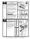
Power Drill
3/16” Drill Bit
7/16” Socket
Driver
None