


Tools Needed:
29
Please Do Not Return This Product To The Store. Contact your local Wayne-Dalton dealer. To find your local Wayne-Dalton dealer, refer to your local
yellow pages business listings or go to the Find a Dealer section online at www.Wayne-Dalton.com
INSTALLATION
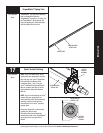
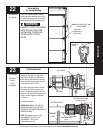
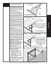
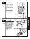
Rear Support Continued...
NOTE: If an idrive
®
opener is installed,
position horizontal tracks one hole above
level when securing it to rear supports.
NOTE: Perforated angle must be attached
to sound framing members and nails
should not be used.
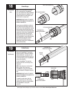
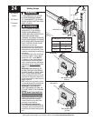
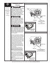
Now, lift door and check it’s balance.
Adjust, if door lifts by itself (hard to pull
down) or if door is difficult to lift (easy to
pull down). Anytime spring adjustments
are made, ratchet pawl knob must be in
the upper position to add/remove required
number of spring turns (refer to step 29).
To adjust springs, only add or remove a
maximum of 3/10 of a turn (three teeth of
ratchet wheel) at a time. Both sides need to
be adjusted equally on double spring doors.
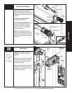
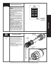
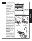
Add Spring Tension: The ratchet wheel is
made of 10 teeth. To add spring tension,
ensure the ratchet and socket is set so that
it will tighten counter clockwise on the right
hand side, and clockwise on the left hand
side. Place the ratchet with 5/8” socket
onto the winding shaft, pull down to add
3/10 of a turn. Watch as three teeth of the
ratchet wheel pass over the pawl, creating
three “clicks”.
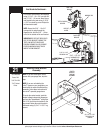
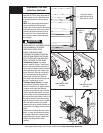
Remove Spring Tension: To remove spring
tension, ensure the ratchet and socket is
set so that it will tighten counter clockwise
on the right hand side and clockwise on
the left hand side. It is recommended that
a regular 5/8” wrench be used. Place the
wrench onto the winding shaft. Pull down
on the wrench to relieve pressure between
the pawl and the ratchet wheel. Push in on
the pawl to allow the three ratchet wheel
teeth to pass by the pawl, as you carefully
allow the wrench to be rotated upward by
the spring tension. Release the pawl to
allow it to engage with the ratchet wheel.
IMPORTANT: BE PREPARED TO HOLD THE
FULL TENSION OF THE SPRING.
IMPORTANT: DO NOT ADD OR REMOVE
MORE THAN 1 SPRING TURNS (1 SPRING
TURN EQUALS 10 TEETH ON RATCHET
WHEEL) FROM THE RECOMMENDED
NUMBER OF TURNS SHOWN ON THE
SPRING TURN CHART.
If the door still does not operate easily,
lower the door into the closed position,
UNWIND SPRING(S) COMPLETELY, and
recheck the following items:
1.) Check the door for level.
2.) Check the TorqueMaster
®
tube and
flagangles for level and plumb.
3.) Check the distance between the
flagangles must be door width plus
3-3/8” to 3-1/2”.
4.) Check the counterbalance cables for
equal tension adjust if necessary.
5.) Rewind the spring(s).
6.) Make sure door isn’t rubbing on jambs.
After door installation is completed and you
have installed an idrive
®
opener,
refer to
Steps 15 thru 32 in your idrive
®
Installation
Instruction/Owner’s Manual.
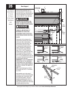
HORIZONTAL
TRACK
BOLT MUST EXTEND INTO THE TRACK
TO SERVE AS A ROLLER STOP
PERFORATED
ANGLE
PERFORATED ANGLE - BOLTED
USING (2) 5/16” X 1-5/8” HEX HEAD
LAG SCREWS TO CEILING MEMBER
AND PARALLEL TO WIDTH OF DOOR.
SPACE LAG SCREWS NO FURTHER
THAN 24” APART.
SOUND FRAMING MEMBERS
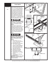
SOUND FRAMING MEMBERS
HORIZONTAL
TRACK
BOLT MUST EXTEND INTO THE TRACK
TO SERVE AS A ROLLER STOP
PERFORATED ANGLE
PERFORATED ANGLE -BOLTED USING
(2) 5/16” X 1-5/8” HEX HEAD LAG
SCREWS TO CEILING MEMBERS
AND PARALLEL TO WIDTH OF DOOR.
ATTACH VERTICAL PERFORATED ANGLE
BETWEEN THE (2) 5/16” X 1-5/8”
HEX HEAD LAG SCREWS, SECURING
PERFORATED ANGLE TO CEILING
MEMBERS.
24”
ANGLE BOLTED TO CEILING
MEMBER AND PARALLEL TO
DOOR
HORIZONTAL
TRACK
ANGLE
BOLT MUST EXTEND INTO THE TRACK
TO SERVE AS A ROLLER STOP
VERTICAL
ANGLE