


VL SERIES STEAMER - ELECTRICAL OPERATION
Pa
g
e 45 of 88
1) HL-3 opens.
2) Fill solenoid de-ener
g
ized and water
stops flowin
g
into tank.
3) HL LED
g
oes out.
4. The water refill cycle will occur whenever the
water level is below the low level probe and will
not affect the operation of either the preheat or
cook cycle.
Boiler Blowdown/drain
1. Main power switch turned OFF.
A. Boiler blowdown sequence starts.
B. The blowdown solenoid valve (N.O.) is de-
ener
g
ized and valve opens to drain the
boiler.
C. Power is removed from all components
except cold water condenser (CWC)
thermostat and solenoid valve. The CWC
thermostat cycles as necessary to lower
the dischar
g
e temperature of the water
and condense steam
g
oin
g
into the drain.
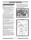
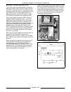
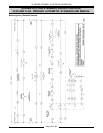
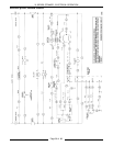
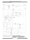
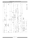
ELECTRIC MODELS
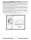
This sequence of operation is written for steamers
with electro mechanical water level controls, Cal-
Code boiler controls option and with Prevent
cookin
g
compartment controls. Refer to schematic
dia
g
ram number 3941 for a boiler control schematic
and 3962 for a schematic and wirin
g
dia
g
ram on
Prevent cookin
g
compartment controls.
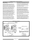
INITIAL FILL AND PREHEAT
1. Conditions.
A. Power switch OFF.
B. Manual reset switch OFF.
C. Cookin
g
timers off.
D. Compartment power switches OFF.
E. Unit connected to correct volta
g
e supply.
1) L1 to one side of the boiler fill
solenoid valve; to one side of the
main and auxiliary contactor(s); to
one side of the power on li
g
ht (red);
to one side of the heat on li
g
ht
(amber); to one side of the timer
motor; to one side of the cold water
condenser solenoid valve; to one side
of the blowdown solenoid valve; to
terminal 1 on the auxiliary low level
control then jumpers connect L1 to
terminal 1 on the differential and low
level controls; to the compartment
controls.
2) L2 to the common terminal on the
blowdown timer relay; to pin 4 on the
boiler ON/OFF switch; to one side of
the manual reset switch; to one side
of the auxiliary switch(s) mounted on
the side of the auxiliary contactor(s);
to the compartment controls.
F. Unit properly
g
rounded. (Boiler and water
level control share a common
g
round)
G. Water supply valve on.
H. Control (cyclin
g
) pressure switch closed.
I. Hi
g
h limit pressure switch closed.
J. Cold water condenser (CWC) thermostat
open.
K. Blowdown solenoid valve (drain) closed
and boiler empty.
L. Compartment doors open.
2. Power switch turned ON. (located on boiler
control box)
A. Power to terminal 2 on the differential
water level control then jumpers connect
to terminal 2 on both the low level cut-off
and auxiliary low level cut-off water level
controls.
B. Power switch indicator li
g
ht (red) comes
on.
C. Boiler fill solenoid valve is ener
g
ized and
boiler be
g
ins to fill.
NOTE: The safety circuit remains de-ener
g
ized
until the water level in the boiler reaches the
low level cut-off probe (minimum level) for the
auxiliary low level cut-off control and the
manual reset switch is pressed. Also, until the
water level in the boiler reaches the low level
cut-off probe (minimum level) for the low level
cut-off control, the low level cut-off control
remains de-ener
g
ized. The heatin
g
elements
will not
come on until the manual rest switch is
pressed these conditions are satisfied.
3. Water level reaches LLCO (low water level cut-
off) probe for the low level cut-off control and to
the auxiliary LLCO probe for the auxiliary low
level cut-off control.
A. Power to terminal 10 on the low level cut-
off and on the auxiliary low level cut-off
control is present. The internal contactor
coil on the water level controls are then
ener
g
ized.
1) The normally open contacts on
terminals 7 and 8 for both the main
and auxiliary low level cut-off controls
close.
2) The main heater contactor(s) are then
ener
g
ized.