


VL SERIES STEAMER - ELECTRICAL OPERATION
Pa
g
e 38 of 88
ELECTRICAL OPERATION
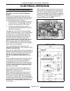
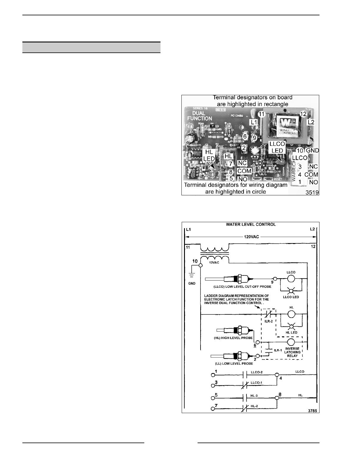
WATER LEVEL CONTROLS
Solid State - Low level Cut-Off & Differential
Control
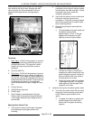
The steamer is equipped with three water level
sensin
g
probes (hi
g
h, low and low level cut-off) and
a sin
g
le water level control board. The water level
control board performs two functions:
1. Provide low level cut-off protection to shut off
the heat source in case the water level drops
below the low level cut-off (LLCO) probe.
2. Performs as a differential level control to
maintain the water level between the low and
hi
g
h water level probes.
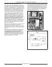
The water level control (WLC) has input volta
g
e
(120VAC) across terminals 11 and 12 which powers
the transformer. On one side of the transformer
secondary, power is provided to the control by a
series path throu
g
h chassis
g
round (terminal 10).
The other side of the transformer secondary
(12VAC) supplies power to one side of the internal
relays LLCO, HL and ILR. As water enters the
boiler, it becomes part of the water level control’s
circuit. When the water level in the boiler reaches a
probe, that circuit is completed.
The inverse latchin
g
relay of the board is de-
ener
g
ized, leavin
g
the ILR-1 (N.O.) and ILR-2 (N.C.)
contacts in their shelf state.
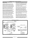
When the main power switch is turned ON, power is
supplied to the WLC board which ener
g
izes the hi
g
h
level (HL) relay and illuminates the HL relay LED.
With the HL-3 contacts closed, the boiler fill
solenoid is ener
g
ized and water be
g
ins fillin
g
the
boiler.
When the water level reaches the low level cut-off
(LLCO) probe, the LLCO relay is ener
g
ized and
illuminates the LLCO LED. With the LLCO-2
contacts closed the heat source is then ener
g
ized.
The LLCO relay will remain ener
g
ized and its LED
will stay lit until the water level in the boiler drops
below the LLCO probe.
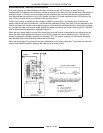
When the water level reaches the low level (LL)
probe, power to terminal 2 on the WLC board is
present but no switchin
g
occurs.
After the water level reaches the hi
g
h level (HL)
probe, the inverse latchin
g
relay of the board is
ener
g
ized and locked throu
g
h the low level probe
(LL) and ILR-1 contacts. With ILR-2 contacts open,
this de-ener
g
izes the HL relay and the HL LED
g
oes
out. With the HL-3 contacts open, the boiler fill
solenoid is de-ener
g
ized, stoppin
g
the flow of water
into the boiler.
When the water level drops below the low level (LL)
probe, power is removed from the inverse latchin
g
relay, the HL relay ener
g
izes throu
g
h ILR-2 and HL
contacts chan
g
e state. The fill solenoid is ener
g
ized
throu
g
h HL-3 to refill the boiler and the HL LED is lit.
The HL relay and LED will to
gg
le ON and OFF
durin
g
a cookin
g
cycle as needed.