


VL SERIES STEAMER - SERVICE PROCEDURES AND ADJUSTMENTS
Pa
g
e 25 of 88
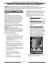
B. With the boiler empty, check the volta
g
e
across terminals 9 & 10. Meter should
read 300 to 350VAC. If volta
g
e is correct
proceed to step 3. If volta
g
e readin
g
is
approximately 30VAC then the internal
contactor is ener
g
ized but the probes are
scaled over and moist and/or have a
dama
g
ed insulator
g
ivin
g
a false readin
g
.
See “Water Level Probes“ listed below for
inspectin
g
and cleanin
g
and “BOILER” for
procedures on boiler inspection, clean-out
and delimin
g
. If you do not read any
volta
g
e, then contactor coil on the water
level control is bad and the control should
be replaced. Check for proper operation
after replacement.
3. If water is in the boiler but is not bein
g
detected
by the water level probes, the probes may need
cleaned and/or boiler delimed. See “Water
Level Probes“ listed below for inspectin
g
and
cleanin
g
and “BOILER” for procedures on
boiler inspection, clean-out and delimin
g
.
4. Turn the power switch OFF and disconnect the
lead wire from each probe. Note the location of
the probes and the number of the wire
connected to it.
A. Check the resistance between the probe
terminal and boiler shell. An open
circuit
should be present when the boiler is
empty. If resistance is present, remove
and inspect the probes as outlined below
under “Water Level Probes”. A resistance
readin
g
should only be measurable
between the probes and boiler shell
(
g
round) when the boiler is full of water.
NOTE: The actual resistance readin
g
will depend on
water quality and probe condition.
5. If after performin
g
steps 1-4 and the control is
not functionin
g
properly, verify the water level
controls operation as outlined in “WATER
LEVEL CONTROLS” under “ELECTRICAL
OPERATION”.
6. After checkin
g
the above items, if the low level
cut off or differential water level control does
not appear to be functionin
g
as described, then
replace the control and check for proper
operation.
Water Level Probes
WARNING: DISCONNECT THE ELECTRICAL
POWER TO THE MACHINE AT THE MAIN
CIRCUIT BOX. PLACE A TAG ON THE CIRCUIT
BOX INDICATING THE CIRCUIT IS BEING
SERVICED.
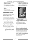
1. Remove the cover over the water level probes
and disconnect the lead wire from each probe.
Note the location of each probe and the
number of the wire connected to it. Remove
each water level probe for examination.
2. If lime scale build up is evident on the probe,
thorou
g
hly clean it removin
g
all deposits from
the probe and insulator. Do not
use any thin
g
abrasive on the insulator; use a soft cloth.
3. Inspect the probes for a cracked or dama
g
ed
insulator. If a probe appears to be dama
g
ed,
replace it with a new one and proceed to step
5. If a probe does not appear to be dama
g
ed
then proceed to step 4.
4. Check throu
g
h the probe socket openin
g
in the
top of the canister assembly for the presence of
water. Water must drain from the probe
canister and if in doubt, pour water into the
canister and observe that it drains quickly. If
water fails to drain from the canister, remove
the cover or canister assembly and clean.
5. Reverse procedure to install and check for
proper operation.
CYCLING AND HIGH LIMIT
PRESSURE SWITCHES
(GAS AND ELECTRIC MODELS)
WARNING: THE FOLLOWING STEPS REQUIRE
POWER TO BE APPLIED TO THE UNIT DURING
THE TEST. USE EXTREME CAUTION AT ALL
TIMES.
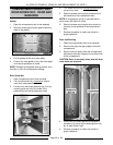
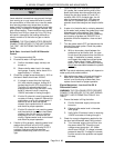
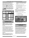
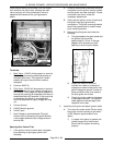
Remove the boiler control box cover as outlined
under “CYCLING AND HIGH LIMIT PRESSURE
SWITCHES (GAS AND ELECTRIC MODELS)” to
access the two controls. The pressure switch on the
ri
g
ht is the cyclin
g
or primary control; the one on the
left is the hi
g
h limit control. They are identical
switches, differin
g
only in their settin
g
s.
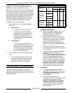
Turn the power ON and let the boiler come up to
pressure. Close and seal one of the compartment
doors, set a time past 5 minutes on the cookin
g
timer, pull the steam control arm handle forward and
turn the compartment power switch ON to exhaust
pressure from the boiler. Observe boiler pressure
g
au
g
e readin
g
s for several cycles and compare
them with the pressure settin
g
s in the chart.
If the readin
g
s differ, adjust the pressure settin
g
s as
described below.