


VL SERIES STEAMER - SERVICE PROCEDURES AND ADJUSTMENTS
Pa
g
e 33 of 88
2) If a spark from i
g
nitor is present but
does not i
g
nite
g
as before the i
g
nition
control module locks out, (90 sec.)
there may not be enou
g
h
g
as in the
line for i
g
nition. Verify the
g
as supply
and
g
as combination control valve
are both on. Turn the i
g
nition control
modules re-set switch OFF then ON
to reset the module. Sparkin
g
should
then resume to i
g
nite
g
as. The
module may need reset several times
before i
g
nition takes place.
3) If i
g
nitor is still not sparkin
g
proceed
to step 3.
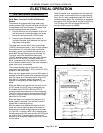
3. Check the i
g
nition control module and
transformer.
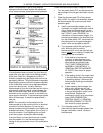
A. Turn the i
g
nition control modules re-set
switch OFF then ON to eliminate a lockout
condition.
B. Check for 24VAC output on the i
g
nition
control module transformer.
1) If 24VAC is present between
terminals 5 & 6 on the i
g
nition control
module but i
g
nitor is not sparkin
g
,
then replace i
g
nition control module
and re-test.
2) If 24VAC is not present then ensure
that transformer is receivin
g
120VAC
input. If i
g
nition control module
transformer is receivin
g
proper
volta
g
e, then replace i
g
nition control
module transformer and re-test.
4. After makin
g
the necessary component
adjustments or replacements, check for proper
operation.
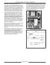
GAS MANIFOLD PRESSURE
ADJUSTMENT
WARNING:
DISCONNECT THE ELECTRICAL
POWER TO THE MACHINE AT THE MAIN
CIRCUIT BOX. PLACE A TAG ON THE CIRCUIT
BOX INDICATING THE CIRCUIT IS BEING
SERVICED.
WARNING:
SHUT OFF THE GAS SUPPLY
BEFORE SERVICING THE UNIT.
1. Open the front cabinet doors and turn the
g
as
combination control valve off.
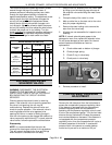
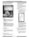
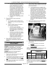
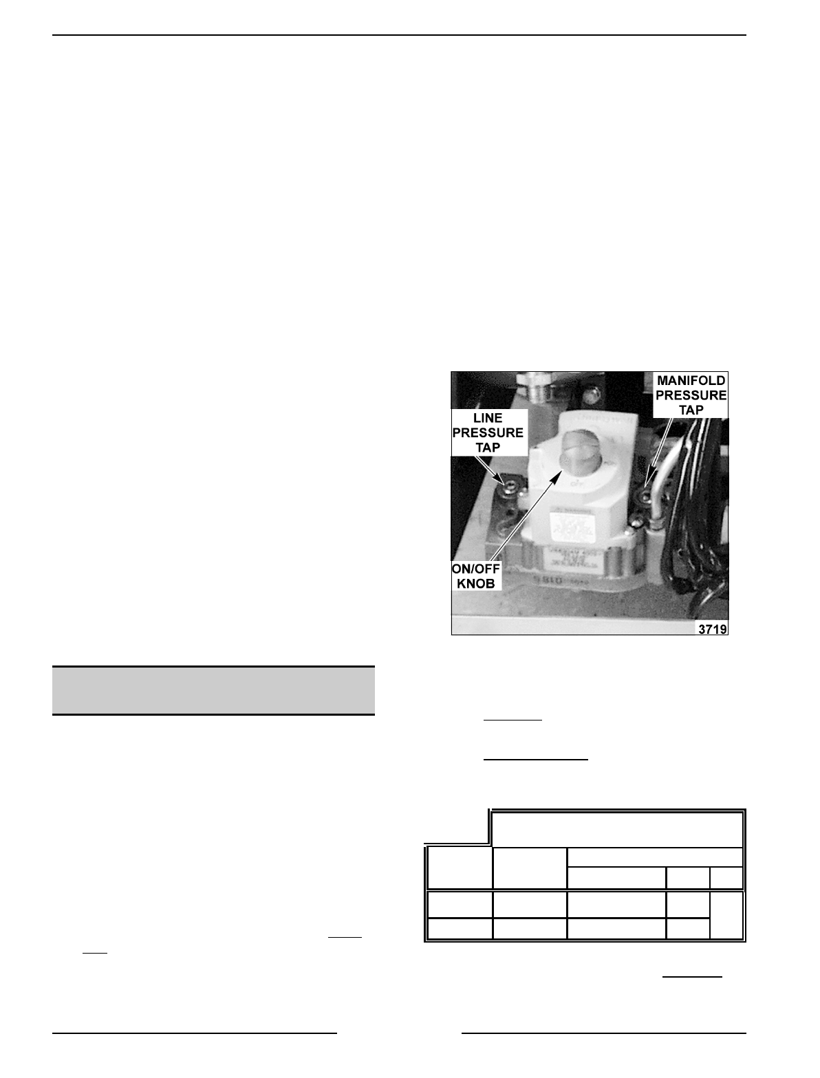
2. To measure the manifold pressure, remove the
1/8 inch NPT plu
g
(pressure tap) on the outlet
side of the valve and attach a manometer.
3. Turn the
g
as combination control valve and the
main power switch to ON.
4. After the burner li
g
hts, compare the manometer
pressure readin
g
to the pressure chart near the
end of this procedure.
A. If other appliances are connected to the
same
g
as line, turn them all ON and check
manometer pressure readin
g
a
g
ain. If the
pressure drops ½ inch water column or
more, then the incomin
g
pressure should
be checked. then the
g
as supply needs to
be checked by the
g
as line installer or the
local
g
as company for adequate sizin
g
.
B. If no other
g
as appliances are connected
to the
g
as line or the pressure does not
drop as described above but the manifold
pressure still requires adjustment, proceed
to step 5.
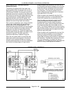
5. Remove the adjustment screw cap to access
the pressure adjustment screw.
6. After the burner li
g
hts, set the pressure as
outlined below.
A. To increase pressure, turn the screw
clockwise
.
B. To decrease pressure, turn the screw
counterclockwise
.
NOTE:
Accurate
g
as pressure adjustments can only
be made with the
g
as ON and the burner lit.
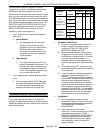
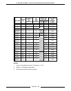
PRESSURE READINGS
(INCHES W.C.)
GAS TYPE MANIFOLD
LINE
RECOMMENDED MIN MAX
Natural 4.0 7.0 5.0
14
Propane 10.0 11.0 11.0
NOTE
: If the incomin
g
line pressure is
less than
the
minimum stated, then the manifold pressure can not
be set correctly.