


VL SERIES STEAMER - SERVICE PROCEDURES AND ADJUSTMENTS
Pa
g
e 32 of 88
Once the pilot flame is confirmed, a 24 volt output
from terminal one will be sent, allowin
g
the main
valve (cyclin
g
) coil of the combination valve to
operate at the request of the cyclin
g
pressure
switch.
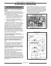
Terminals:
1. Main Valve
- 24VAC will be present on terminal
#1 with the pilot sensin
g
electrode sensin
g
an
adequate pilot fame. This output will remain
present as lon
g
as the pilot flame remains
adequate.
2. Common (MV/PV).
3. Pilot Valve
- 24VAC will be present on terminal
#3 at the instant an input volta
g
e is supplied to
the module. This volta
g
e will remain present on
terminal #3 providin
g
an adequate pilot flame is
established within 90 seconds. In the event that
an adequate pilot flame is not established
within 90 seconds this output volta
g
e will drop
out.
4. Ground (burner).
5. 24VAC Neutral (
g
round).
6. 24VAC Input.
7. Hi
g
h Volta
g
e to spark electrode (The pilot
flame current is sensed by the I
g
nitor Module
via the spark electrode hi
g
h volta
g
e wire and
terminal #9).
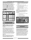
Spark Ignition Control Test
1. If the i
g
nition control module does not appear
to be sparkin
g
to i
g
nite
g
as, perform the
followin
g
:
A. Check to ensure that all electrical terminal
connections on the i
g
nition control module
and the i
g
nitor are clean and ti
g
ht. If loose
connections are found, make the
necessary adjustments.
B. Verify that the i
g
nition control module and
the i
g
nitor have
g
ood
g
round wire
connections. The i
g
nitor mountin
g
bracket
should have
g
ood metal to metal contact
to its mountin
g
surface.
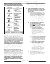
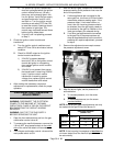
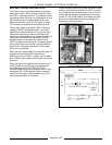
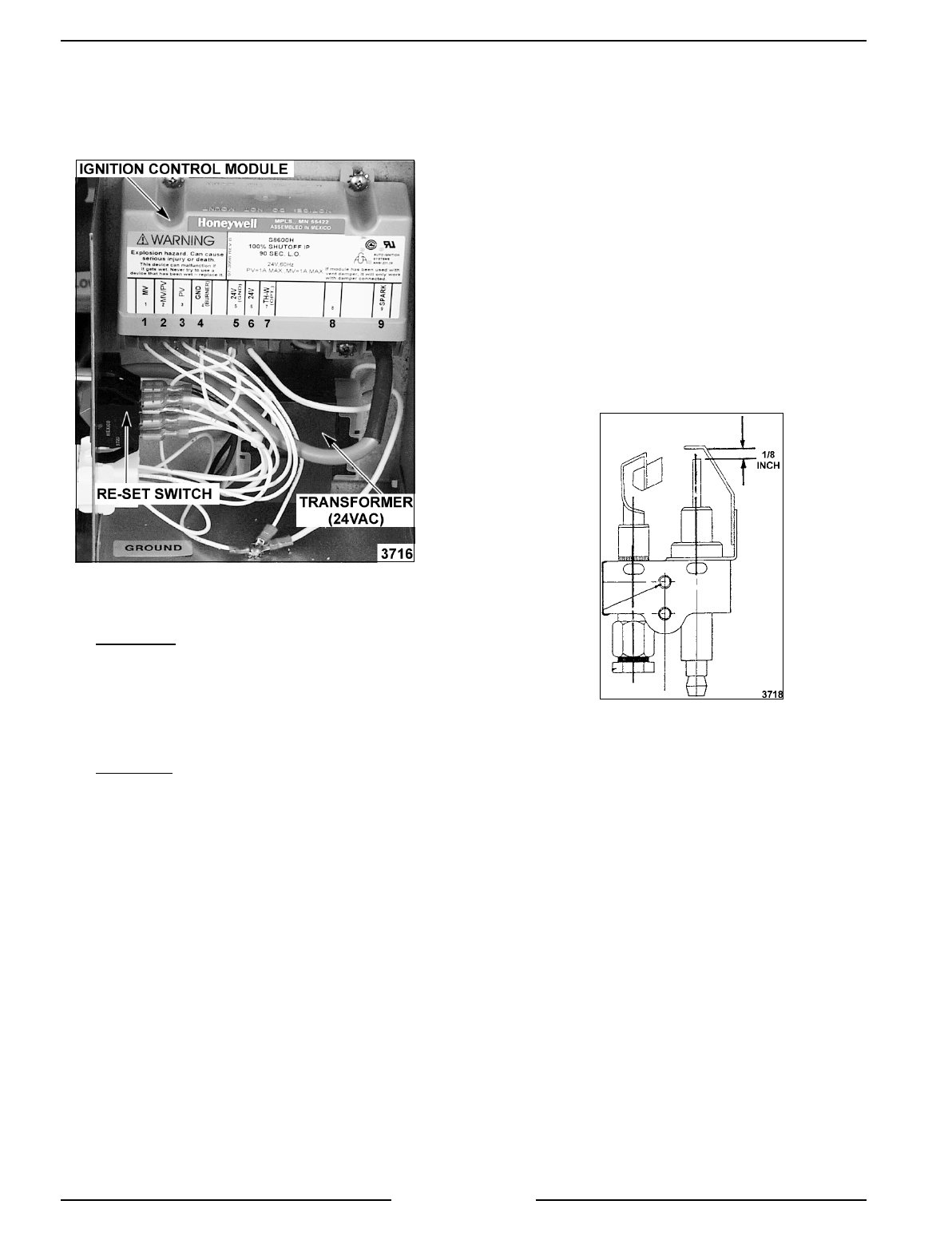
C. Remove the pilot i
g
nitor and check the
followin
g
:
1) The
g
ap between the spark probe and
the
g
round clip should be
approximately 1/8 inch. If the
g
ap
appears to be excessive or poor
sparkin
g
is occurrin
g
then adjust.
2) Inspect the ceramic flame rod
insulator for cracks or evidence of
exposure to extreme heat, which can
permit leaka
g
e to
g
round. If either of
these conditions exist, then replace
the pilot i
g
nitor and re-test.
3) Check the i
g
nition cable for ti
g
htness
or dama
g
ed insulation. If the i
g
nition
cable appears to be dama
g
ed, then
replace it and re-test.
2. Install the pilot i
g
nitor and attach i
g
nition cable.
A. Turn the main power switch ON and verify
the i
g
nition control modules re-set switch
is ON. Observe spark condition from
i
g
nitor.
1) If a spark from i
g
nitor is present and
i
g
nites the
g
as from the pilot and
burner then the system is workin
g
properly.