


VL SERIES STEAMERS - REMOVAL AND REPLACEMENT OF PARTS
Pa
g
e 17 of 88
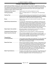
WATER LEVEL CONTROLS -
LOW LEVEL CUT OFF AND
DIFFERENTIAL
WARNING:
DISCONNECT THE ELECTRICAL
POWER TO THE MACHINE AT THE MAIN
CIRCUIT BOX. PLACE A TAG ON THE CIRCUIT
BOX INDICATING THE CIRCUIT IS BEING
SERVICED.
Solid State
1. Open the cabinet base doors.
2. Remove the two screws at the top of the boiler
control box and allow cover to drop down.
3. Water level control is mounted on the back
side of cover.
4. Disconnect lead wires from the board and
remove the water level control.
5. Reverse procedure to install and check for
proper operation.
Electro Mechanical
1. Open the cabinet base doors.
2. Remove the two screws from the left and ri
g
ht
side of the water level control box and lift cover
off.
3. Disconnect lead wires from the control bein
g
replaced and remove.
4. Reverse procedure to install and check for
proper operation.
WATER LEVEL GAUGE
ASSEMBLY
WARNING:
DISCONNECT THE ELECTRICAL
POWER TO THE MACHINE AT THE MAIN
CIRCUIT BOX. PLACE A TAG ON THE CIRCUIT
BOX INDICATING THE CIRCUIT IS BEING
SERVICED.
1. Open the cabinet base doors and remove the
ri
g
ht side panel.
2. Close the valve at the top and at the bottom of
the
g
au
g
e assembly.
3. Unscrew the packin
g
nuts at the top and bottom
of the
g
lass tube.
4. Slide the
g
lass tube upwards until the bottom of
the tube is clear of the fittin
g
and lift it out.
5. When reinstallin
g
the tube use new sealin
g
washers. Do not over ti
g
hten the packin
g
nuts;
it could break the
g
au
g
e
g
lass.
6. Open the top and bottom valves and check for
proper operation.
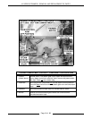
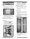
CYCLING AND HIGH LIMIT
PRESSURE SWITCHES
(GAS AND ELECTRIC MODELS)
WARNING:
DISCONNECT THE ELECTRICAL
POWER TO THE MACHINE AT THE MAIN
CIRCUIT BOX. PLACE A TAG ON THE CIRCUIT
BOX INDICATING THE CIRCUIT IS BEING
SERVICED.
1. Open the cabinet base doors and remove the
left side panel.
2. Remove the two screws at the top of the boiler
control box and allow cover to drop down.
3. The pressure switches are located at the rear of
the box. The pressure switch on the ri
g
ht is the
cyclin
g
or primary control; the one on the left is
the hi
g
h limit control. They are identical
switches, differin
g
only in their settin
g
s.
4. Remove the cover from the pressure switch
bein
g
replaced and disconnect the lead wires.
5. Disconnect the pressure fittin
g
s at the bottom
of the switch.
6. Remove the mountin
g
screws on the back side
of the control box and lift out the pressure
switch.
7. Preset the new pressure switch to the
approximate cut-out (off) and cut-in (on) set
points before installin
g
. See the boiler pressure
chart under “CYCLING AND HIGH LIMIT
PRESSURE SWITCHES (GAS AND
ELECTRIC MODELS)” in “SERVICE
PROCEDURES AND ADJUSTMENTS”.
8. Reverse procedure to install.
9. Adjust the pressure switch(s) final set points as
outlined under “CYCLING AND HIGH LIMIT
PRESSURE SWITCHES (GAS AND
ELECTRIC MODELS)” in “SERVICE
PROCEDURES AND ADJUSTMENTS” and
check for proper operation.