


VL SERIES STEAMER - ELECTRICAL OPERATION
Pa
g
e 42 of 88
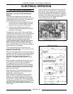
SEQUENCE OF OPERATION
GAS MODELS
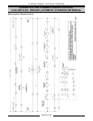
This sequence of operation is written for steamers
with electronic i
g
nition, solid state water level
controls, CSD-1 (code) boiler controls option and
with Prevent cookin
g
compartment controls. Refer
to schematic dia
g
ram numbers 3928 and 3929 for a
boiler control schematic and 3962 for a schematic
and wirin
g
dia
g
ram on Prevent cookin
g
compartment controls.
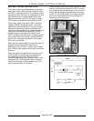
Initial Fill and Preheat
1. Conditions.
A. Power switch OFF.
B. I
g
nition module reset switch ON
C. Cookin
g
timers off.
D. Compartment power switches OFF.
E. Unit connected to correct volta
g
e .
1) L1 (HOT) to one side of the cookin
g
compartment controls; to one side of
the cold water condenser thermostat;
to one side of the power ON/OFF
switch.
2) L2 (NEUTRAL) to one side of the
cookin
g
compartment controls; to one
side of the cold water condenser
(CWC) solenoid valve; to one side of
the power ON/OFF switch.
F. Unit properly
g
rounded. (Boiler and water
level control share a common
g
round)
G. Water supply valve on.
H. Gas supply valve on.
I. Gas combination control valve ON.
J. Control (cyclin
g
) pressure switch closed.
K. Hi
g
h limit pressure switch closed.
L. Cold water condenser (CWC) thermostat
open.
M. Blowdown solenoid valve (drain) open and
boiler empty.
N. Compartment doors open.
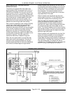
2. Power switch turned ON. (located on boiler
control box)
A. Power switch indicator li
g
ht (red) comes
on.
B. Hi pressure indicator li
g
ht (amber) comes
on.
C. Low water level indicator li
g
ht (amber)
comes on.
NOTE:
The hi
g
h pressure indicator li
g
ht will remain
on and the safety circuit de-ener
g
ized until boiler
steam pressure is within operational limits (hi
g
h limit
pressure switch closed) and the manual reset button
is pressed. The low water indicator li
g
ht will remain
on and the safety circuit de-ener
g
ized until the water
level in the boiler reaches the low level cut-off
probes (minimum level) for the water level control,
the auxiliary low level cut-off control and the manual
reset switch is pressed. The
g
as burners will not
li
g
ht until these conditions are satisfied.
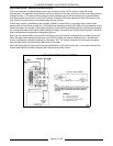
D. Water level control (WLC) is powered.
1) Hi
g
h level (HL) relay is ener
g
ized,
HL-3 (N.O.) contacts close and HL
LED li
g
hts up.
2) The inverse latchin
g
relay of the
board remains de-ener
g
ized, leavin
g
the ILR-1 (N.O.) and ILR-2 (N.C.)
contacts in their shelf state.
E. Auxiliary low water level cut-off control is
powered, LLCO-2 (N.O.) contacts remain
open.
F. With the HL-3 and ILR-2 contacts closed,
the fill solenoid is ener
g
ized and water
boiler be
g
ins fillin
g
.
G. Blowdown solenoid valve is ener
g
ized and
closes.
H. I
g
nition module be
g
ins sparkin
g
to li
g
ht
pilot after a 3 second delay.
1) If pilot i
g
nition is established (pilot lit)
then a micro amp flame sense
current is sent back to the i
g
nition
control module throu
g
h the i
g
nition
cable. Sparkin
g
stops, pilot remains
lit and is ready to i
g
nite burners.
2) If pilot i
g
nition is not established after
90 seconds, sparkin
g
stops and the
i
g
nition control module locks out
power to the combination
g
as valve
(pilot valve and main valve remain
closed). The module remains locked
out until the reset switch on the
i
g
nition control module box is
switched to OFF then ON to re-start
the i
g
nition trial cycle.
NOTE:
If the modules re-set switch is in the OFF
position, no sparkin
g
will occur or if it’s turned OFF
while idlin
g
or cookin
g
, then pilot and burners will
g
o
out and not re-i
g
nite upon call for heat by the cyclin
g
pressure switch.