


VL SERIES STEAMER - SERVICE PROCEDURES AND ADJUSTMENTS
Pa
g
e 30 of 88
NOTE: If adjustments in
g
as or pilot pressure
settin
g
s are made, always replace the adjustment
cover screw to assure proper
g
as control operation.
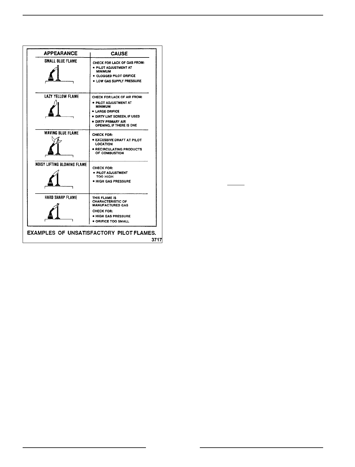
If the adjustment does not result in a pilot flame of
proper size, then
g
as mi
g
ht not be flowin
g
properly
to the pilot. Check for a plu
gg
ed pilot orifice, a
kinked or plu
gg
ed pilot
g
as supply tube and for low
g
as supply pressure. The pilot operates unre
g
ulated
at
g
as supply pressures while the pressure re
g
ulator
in the combination control valve re
g
ulates pressure
to the main burners only. Visually check the
thermocouple tip (hot end) and tube lead for kinks or
pinches that mi
g
ht be causin
g
a short between the
tube and the wire inside. Also, check the threaded
connector tip for corrosion, tarnish or dirt which can
cause a poor connection. If the thermocouple shows
either of these si
g
ns, it should be replaced with a
new one.
NOTE: The connection of the tubin
g
from the
thermocouple tip to the control valve is an electrical
connection and must be clean. Do not use any
sealin
g
compound on the threads or over ti
g
hten the
threaded connection. Fin
g
er ti
g
hten the nut plus 1/4
turn with a wrench. Over ti
g
htenin
g
the nut could
crush the insulator, shortin
g
the thermocouple.
If the pilot flame is correct and there are no drafts,
then the problem is in the thermocouple output
volta
g
e or the
g
as solenoid valve in the combination
control.
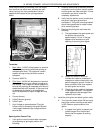
Check the thermocouple output volta
g
e as follows:
1. Turn the power switch OFF and disconnect the
thermocouple from the
g
as combination control
valve.
2. Check the thermocouple DC millivolt output
with a VOM. If a meter is not available, replace
the thermocouple with a new one and check
operation a
g
ain.
A. Install a thermocouple adaptor into the
connection on the
g
as combination control
valve. Screw the thermocouple in to the
adaptor then connect the meter leads to it.
See “TOOLS” under “GENERAL” for
information on thermocouple adaptor. If a
thermocouple adaptor is not available then
turn the power switch OFF, disconnect the
thermocouple from the
g
as combination
control valve and proceed to step 2D.
B. Turn the power switch ON and li
g
ht the
pilot. Allow the pilot to heat the
thermocouple for one to two minutes and
take a closed
circuit readin
g
. Compare the
readin
g
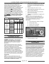
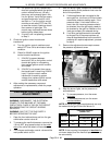
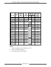
s with the chart below.
1) If the readin
g
is less than the
minimum or thermocouple is not
operatin
g
as described, replace the
thermocouple as outlined under
“PILOT AND THERMOCOUPLE
ASSEMBLY (GAS MODELS)” in
“REMOVAL AND REPLACEMENT
OF PARTS” then check for proper
operation.
2) If the readin
g
is within the ran
g
e listed
in the chart below then thermocouple
is operatin
g
properly. Reconnect the
thermocouple to the
g
as combination
control valve.
3) If after replacin
g
thermocouple, the
pilot or main burners are still not
functionin
g
properly, then a problem
in the
g
as combination control valve
exists as well. Replace the
combination control valve as outlined
under “GAS COMBINATION
CONTROL VALVE” in “REMOVAL
AND REPLACEMENT OF PARTS”
then check for proper operation.
C. Turn the power switch OFF and
disconnect the thermocouple adaptor from
the
g
as combination control valve and
thermocouple.