


VL SERIES STEAMER - SERVICE PROCEDURES AND ADJUSTMENTS
Pa
g
e 26 of 88
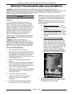
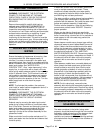
Two slotted and square headed adjustment screws
extend throu
g
h the top of the switch case. A
pressure scale and indicatin
g
pointers are visible
throu
g
h the si
g
ht
g
lass window to indicate the
approximate pressure settin
g
. The adjustment screw
directly above the ri
g
ht side pointer chan
g
es the
cut-out (off) set point and the adjustment screw
directly above the left
side pointer chan
g
es cut-in
(on) set point. Adjust the screw to obtain the proper
cut-out (off) settin
g
first, then adjust the other screw
to obtain the proper cut-in (on) settin
g
. Turn the
screw clockwise
to increase the pressure settin
g
and
counterclockwise
to decrease the pressure settin
g
.
The pressure settin
g
s for each switch are listed
below.
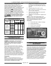
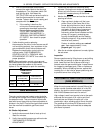
BOILER PRESSURE SETTINGS (PSI)
CONTROL
TYPE
VL
MODELS
CYCLING HIGH
LIMIT
ON OFF ON OFF
With
Compartment
Pressure
Regulating Valve
PS
911615
AS
SS
MS
With-Out
Compartment
Pressure
Regulating Valve
AS
46215SS
MS
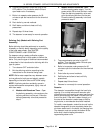
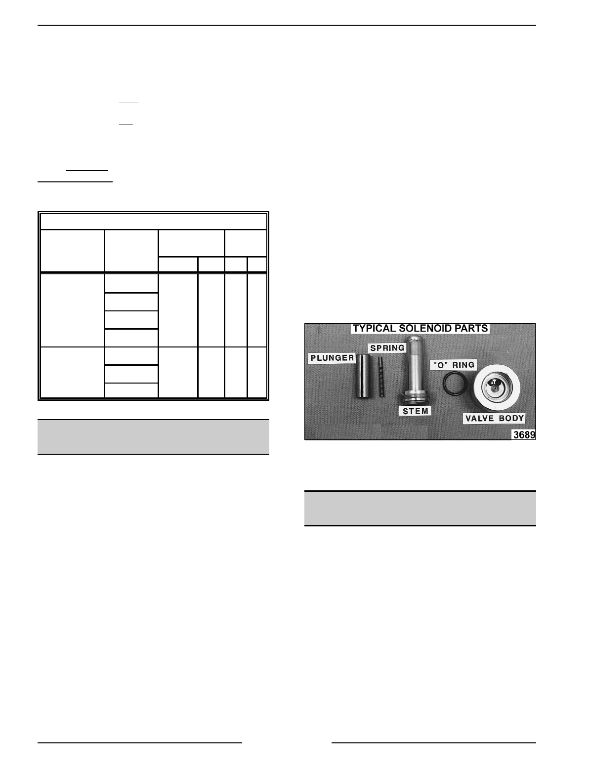
FILL AND COLD WATER
SOLENOID VALVES
WARNING:
DISCONNECT THE ELECTRICAL
POWER TO THE MACHINE AT THE MAIN
CIRCUIT BOX. PLACE A TAG ON THE CIRCUIT
BOX INDICATING THE CIRCUIT IS BEING
SERVICED.
Check to assure the solenoid valve is receivin
g
power. If the solenoid valve is receivin
g
power but
the valve is not openin
g
, the coil may be
malfunctionin
g
. Replace the solenoid valve and
check for proper operation. If the solenoid valve is
receivin
g
power and the valve appears to be
openin
g
but little or no water is flowin
g
throu
g
h it,
then the valve ports may be clo
gg
ed with debris or a
valve component malfunctionin
g
. To check solenoid
valve further, follow the procedure outlined below.
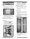
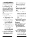
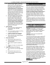
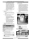
Disassembly
NOTE:
It is recommended that the valve be
removed for cleanin
g
as outlined in this procedure.
This will prevent dama
g
e to the lines and fittin
g
s
when the stem is removed from the body.
1. Remove the coil assembly from the valve stem
by liftin
g
up on the retainin
g
cap at the top of
the solenoid valve and slidin
g
the metal cover
plate off.
2. Clamp the body of the valve in a vise.
3. Mark a scribe line on the stem nut to the valve
body for proper reti
g
htenin
g
.
4. Remove the stem lockin
g
nut to remove the
stem from the valve body.
5. All parts are now accessible for inspection and
cleanin
g
.
NOTE:
If internal solenoid parts appear to be
dama
g
ed or worn, then replace the solenoid valve.
Do not reuse dama
g
ed or worn parts. No internal
solenoid parts are available as a service
replacement.
A. Check rubber seal on bottom of plun
g
er.
B. Check plun
g
er sprin
g
.
C. Check O-rin
g
in valve body.
D. Check ports in valve body.
6. Reverse procedure to install.
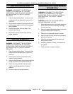
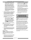
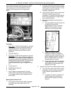
COMPARTMENT PRESSURE
ADJUSTMENT
Remove the left side panel from the boiler base to
access the compartment pressure re
g
ulatin
g
valve.
If the steamer is equipped with the compartment
pressure re
g
ulatin
g
valve and the steamer is
operatin
g
, set the pressure re
g
ulatin
g
valve to read
6 psi on the compartment
g
au
g
e. Turn the hex head
screw at the top clockwise to increase the pressure
and counterclockwise to decrease. If the steamer is
not equipped with the compartment pressure
re
g
ulatin
g
valve, then the compartment will cycle at
the same pressures of the boiler. A mechanical
pressure relief valve serves as a safety backup
control and is pre-set for a maximum of 8 psi.