


VL SERIES STEAMERS - GENERAL
Pa
g
e 13 of 88
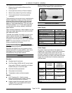
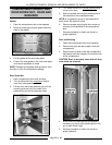
COOKING COMPARTMENT CONTROLS
The top half of the steamer consists of two to three separate cookin
g
compartments dependin
g
on the model.
Each compartment functions independently with its own set of controls. Power is supplied to the controls throu
g
h
the compartment power switch and the cookin
g
timer control micro switch contacts. Prevent and Automatic
models have a load compensatin
g
thermal switch that prevents the controls from receivin
g
power until the
compartment reaches 180°F to close the switch.
Compartment Power Switch......
Supplies power to the cookin
g
compartment controls.
Cooking Light (Red) ............
When lit, indicates steamer is in a cookin
g
cycle. (All models except
manual)
Cooking Timer .................
Use to set desired cookin
g
cycle time between 0-60 minutes. Ener
g
izes
the buzzer when time expires (All models except manual). On Prevent
models, also de-ener
g
izes the steam exhaust solenoid valve one minute
before the end of a cook cycle to allow compartment ventin
g
.
Buzzer .......................
Si
g
nals end of a cook cycle, must be turned off manually. (All models
except manual)
Steam Exhaust Solenoid Valve . . .
A normally open valve that allows full compartment ventin
g
of air and
condensate up to 180°F durin
g
compartment heat up and “limited free
ventin
g
” after ener
g
ized by the closin
g
of the thermal switch. The valve
remains closed to allow compartment pressurization to 6 psi until one
minute before the end of a cook cycle at which point the timer control
micro switch contacts (SW2) chan
g
e state and de-ener
g
ize the valve to
vent the compartment of pressure and steam. (prevent models)
Steam Header Inlet (manifold) ....
Main steam supply line from the boiler for each cookin
g
compartment.
Supplies steam to the manual steam
g
ate valves.
Compartment Pressure Gauge ....
Indicates the amount of steam pressure in cookin
g
compartments.
Steam Control Arm Solenoid .....
When ener
g
ized, en
g
a
g
es the lift arm (plun
g
er) to raise the steam
control arm off of the catch, allowin
g
it to return to its rear position. This
closes the steam inlet
g
ate valve and opens the steam exhaust
g
ate
valve. (prevent, automatic and standard models)
Thermal Switch
(Load Compensator) ............
Controls power to the preheat cycle components. Turns the cookin
g
li
g
ht
on, ener
g
izes the steam exhaust solenoid valve and ener
g
izes the
cookin
g
timer motor to start timin
g
, after the compartment reaches
180 F. (prevent and automatic models)
Steam Gate Valves .............
Manual valves actuated by the steam control arm. Allows steam to flow
into the cookin
g
compartment throu
g
h the inlet steam
g
ate valve when
the arm is in a forward position and exhaust the steam throu
g
h the
exhaust steam
g
ate valve when the arm is at the rear. Prevent models
use a steam exhaust solenoid valve to exhaust the steam and a sin
g
le
steam
g
ate valve as the steam inlet. The automatic, standard and
manual models use one steam
g
ate valve to exhaust the steam and
one additional steam
g
ate valve as the steam inlet.
Steam Trap (Condenser) .........
Exhausts air and condensate from compartment durin
g
preheat until the
compartment temperature reaches approximately 180 F. The bellows
then close, stoppin
g
the exhaust. (all models except prevent)