


VL SERIES STEAMERS - REMOVAL AND REPLACEMENT OF PARTS
Pa
g
e 18 of 88
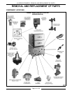
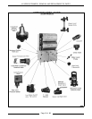
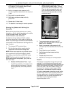
BOILER ASSEMBLY
WARNING:
DISCONNECT THE ELECTRICAL
POWER TO THE MACHINE AT THE MAIN
CIRCUIT BOX. PLACE A TAG ON THE CIRCUIT
BOX INDICATING THE CIRCUIT IS BEING
SERVICED.
WARNING:
SHUT OFF THE GAS BEFORE
SERVICING THE UNIT.
WARNING:
ALL GAS JOINTS DISTURBED
DURING SERVICING MUST BE CHECKED FOR
LEAKS. CHECK WITH A SOAP AND WATER
SOLUTION (BUBBLES). DO NOT USE AN OPEN
FLAME.
1. Blow down the boiler and allow to cool, if
necessary.
2. Ensure that all utilities to the steamer are off
and disconnected. Drain any excess water from
the boiler.
3. Disconnect the steam supply line, power leads
and drain lines from the cookin
g
compartment
top to the boiler base.
4. Disconnect all plumbin
g
connections and power
leads from the components inside the control
boxes that would obstruct the removal of the
boiler throu
g
h the front of the base, then
remove those control boxes.
5. Disconnect the remainin
g
plumbin
g
and
electrical connections from the boiler to the
controls.
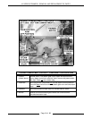
6. Remove the screws holdin
g
the flue and flue
collector to the base.
7. Remove the anchor screws holdin
g
the boiler to
the frame. Slide the boiler forward. The burner
box, anchored only by the boiler, must be
prevented from slidin
g
forward with the boiler.
8. Reverse procedure to install a new boiler and
check for leaks and proper operation.
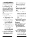
HIGH LIMIT THERMOSTAT
WARNING:
DISCONNECT THE ELECTRICAL
POWER TO THE MACHINE AT THE MAIN
CIRCUIT BOX. PLACE A TAG ON THE CIRCUIT
BOX INDICATING THE CIRCUIT IS BEING
SERVICED.
1. Open the cabinet base doors.
2. Electric models only - for
g
as models proceed
to step 3.
A. Newer Models
- are not equipped with a hi
limit thermostat but rely on the Hi limit
pressure switch instead.
B. Older Models
- the hi
g
h limit thermostat is
located behind the contactor box cover.
On electric boilers with two heatin
g
elements, the thermostat is connected to
one of the heatin
g
element lu
g
s. On
electric boilers with four heatin
g
elements,
the thermostat is located on an aluminum
plate between the center pair of elements
at the top of the elements. Remove the
thermostat lead wires and mountin
g
nuts,
replace thermostat and check for proper
operation.
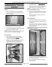
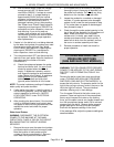
3. Gas Models only.
A. Remove the thermostat cover which is
located on the front of the boiler.
Disconnect the thermostat lead wires and
remove the nuts securin
g
the hi
g
h limit
thermostat to the boiler surface.
4. Reverse procedure to install and check for
proper operation.