


6
Follow the connections above for mains 1 using TB28. Fuse positions
are F3 and F4 for mains 2.
Earth bonding should be to the earthing lug on the mounting plate.
Mains power is MOV protected. Although the Model 12B uses jumper
set dual primary toroidal transformers, do not attempt to change factory
set mains voltage level unless the MOV’s are also changed to the proper
value.
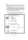
If a door mounted local display or 4-20 mA loop output was specified, a
ribbon cable connects it to the connector at fig 6, loc 14. Do not use this
connector for any other purpose.
Keep-Outs (refer to fig 6, loc 5 and 16)
Note: Failure to heed these “keep-out” areas may damage the
electronics.
The terminal blocks at the upper left are for factory cascading level logic
– do not use for any purpose. Do not connect any wiring to these
terminal blocks.
The programming pins at the lower right are for the CPLD logic block –
do not use for any purpose. Do not store flash jumpers on these pins.
2.6.3 Display Panel (refer to fig 6, loc 15)
External display panel(s) are connected to the Electronic Module by a
16-20 AWG multi-conductor cable. Shielding is required if electrical
conductors other than those for the Model 12B low voltage display share
the same wiring conduit. Do not use extra cable leads for anything
except display module wiring. Use of these cables for other than what
they were intended may cause damage to the electronics.
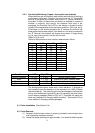
The number of conductors required between Electronics and Display
Panel for your system can be calculated as follows:
Minimum conductors required = Number of probes x 2 + 2 (common) +
2 (fault LED’s).
Therefore, a twelve probe system requires (12 x 2 + 2 +2) = 28
conductors.
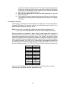
When several display modules are used a maximum of one local and
one remote or two remotes may be directly driven. For more than two,
the displays must be independently powered models. Each module may
be connected in parallel to the Electronic Module terminal strip or daisy
chained from the terminal strip of a preceding display module. Care must
be taken to match the corresponding terminal connections. For daisy
chained connections use heavier gage wire. A smaller remote display
(suitable for desk mounting) is also available.
Light emitting diodes (LED’s) are used on the display module. These
LED’s have an expected 20+ year life and can be replaced only on a
modular basis.