


8
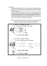
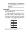
2.6.7 Probe Wiring (refer to fig 6, loc 4)
Each electronic module will support a maximum of twelve probes. Each
probe input to the module may have two wires. These are probe wire
(electrode marked “E” = minimum wiring required with all systems) and a
open/short sense wire, marked “S” (optional). Wiring at the probe is via
the crimp type eyelet supplied with each probe. If the eyelet is not used
intermittent operation may result. At least two ground wires must be
connected to the water column ground. Units with more than 12 probes
use two or more electronic modules in a larger enclosure. The number of
conductors required between the water column and Electronics for your
system may be calculated as follows:
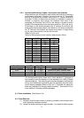
2.6.7.1 Basic Systems (wired only to “E” on the terminal block)
Minimum conductors required = Number of probes + 2
(ground)
Therefore, a twelve probe system requires (12 + 2) = 14
conductors.
2.6.7.2 Systems with Open / Short Option (two wires at each
probe. One from probe to “E” on the terminal block, the
other to “S” on the terminal block.)
Minimum conductors required = Number of probes x 2 + 2
(ground)
Therefore, a twelve probe system with open/short option
requires (12 x 2 + 2) = 26 conductors.
Note: If this option was specified and is NOT
wired as described in
2.6.7 and 2.6.7.2, the electrical fault indication and relay will
continuously indicate fault.
3.0 Startup and Operation
3.1 Water Column
To place the water column in service the following procedure is recommended:
(1) Inspect the water column to ensure that all the probes are installed and the
associated wiring is correct and all connections are secure. Wiring should
be neatly routed and any contact between the high temperature water
column body or the probe cover should be avoided.
(2) Open the blowdown valve.
(3) Crack the steam block valve and warm up the water column for a period of
3 to 5 minutes with low velocity steam.
(4) At the end of the warm-up period, close the blowdown valve and then fully
open the steam valve.
(5) The water connection block valve should now be opened, or alternately, if
this valve is left closed, the vessel will fill with condensate allowing the
operating range to be verified.
(7) The water block valve must then be fully opened.