


1
INSTALLATION, OPERATION and MAINTENANCE MANUAL
FOR PENBERTHY Model 12B
1.0 Description
The Penberthy Model 12B is an accurate and ultra-reliable instrument for detection of
steam/water presence in subcritical pressure steam generators. The unit provides up to
12 channels per unit (cascadable) for steam/water indication and is complete with
control outputs and internal system fault monitoring, Local and Remote indication and
Level Fault output. Prior to performing any work, personnel responsible for the
installation of the system should read these instructions and become familiar with the
unit. There is a patent pending on the detection and verification circuitry.
Two functional options covered by this I.O.M. may be specified. Check purchasing
documents and verify that the unit received has the options specified.
1.1 Independent Power Line Inputs (a.k.a. dual transformer option) provides
redundancy throughout the entire system.
1.2 Open/short detection
If both options are specified, the unit has at minimum either error detection or double
redundancy for its functions and complies with ANSI/ISA S84.01 – 1996 “Safety
Instrumented Systems”.
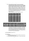
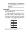
The contract drawing supplied for each installation specifies the tapping point spacing
on the water column, the number of probes and their positioning.
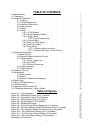
This I.O.M. is organized so that article 2 describes the essentials of installation and
wiring to allow initial turn-on. Articles 3 and 4, covering the same basic subjects, may
seem redundant but describe the details of operation beyond initial turn-on. They should
be perused to maximize the utility of the Model 12B.
2.0 Supply & Installation
2.1 Packing
Prior to installing this equipment clean all packing material from around the unit
and inspect for any damage that may have occurred during shipment. Any
claims for loss or damage must be filed by the purchaser with the carrier. A copy
of the bill of lading and freight bill will be supplied on request by
TV&C – Prophetstown.
2.2 Wiring Requirements
All wiring shall be terminated in a screw type terminal block, a screwed crimp-on
terminal or a screwed lug point.
All wiring for mains in and control relays out shall be dressed away from all
probe and display wiring, bundled and tie wrapped to maintain separation.
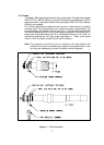
Probes and their wiring that are in steam/vapor are essentially antennas and are
susceptible to noise pick-up. To reduce RFI/EMI pick-up, a cable with an overall
shield should be used for the probe/junction box to electronic module
connections. This is a low current line so small wire diameters are acceptable.
The maximum distance is 300’ [91M], refer to section 2.3 for other details.
Remote display wiring should be limited to 1000’ [305M]. Since I•R loss is the
distance limiter – larger wire will allow longer distances. The low level signals
used suggest that an overall shield on this cable is prudent. If the installation is
to be in an area with high electrical noise or to fully comply with EMC directives,