


9
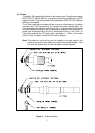
(8) Visually check all the probes for any sign of leaks. Replacement of the probe
cover using the ¼” socket head cap screws will complete the commissioning
of the water column.
(9) The metallic sensing tip of any probe may self-passivate or the probe
insulator may retain a slightly conductive film from processing. A “hot start”
as outlined above will clear any residual passivation or coating. Attempting to
commission a Model 12B using cold water, such as during a hydrostatic test,
cannot guarantee proper probe wetting. The display/relays may therefore
generate a random output commonly called “checkerboarding”. Pre-cleaning
the probes (see section 5.2 (3)) will also eliminate this potential
commissioning problem.
(10) Isolation and blowdown valves should be carefully selected and installed as
outlined in ASME Power Boiler Code, Section 1. Yarway Welbond valves,
Series 5600, are recommended.
(11) During vessel blowdown, isolation or testing, some form of interlocking
bypass of the high and low water control outputs may be required to avoid
boiler tripping.
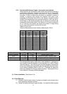
3.2 Electronic Module Sensitivity Control
Inspect the module to ensure that all electrical connections are made and
properly protected. The sensitivity required for the water conductivity range to be
detected should have been specified when the system was ordered, if not, the
default sensitivity of 10 – 100 μS was supplied. If the sensitivity is not correct,
proper replacement resistor packs should be obtained by contacting TV&C –
Prophetstown with the conductivity of water used. The proper resistor packs are
placed into sockets at R444 and R445 (ref: fig 6, loc 6). These are standard dual
in-line (DIP) IC type sockets. Do not bend any resistor pack lead during insertion.
Note: All channels will be set to the same conductivity range.
The factory default setting is: Conductivity 10 - 100μS nominal.
After setting the sensitivity, power may be supplied to the unit by use of the
external circuit breaker. The unit is now operational.
3.3 System Monitor (a.k.a. Electrical Fault)
The Model 12B is equipped with a SPDT fault annunciating relay that monitors
critical internal electronic circuitry. The fault relay is de-energized when a fault is
present. If the mains power to the device is lost or if one of the three conditions
listed below were to occur the fault relay will de-energize.