


14
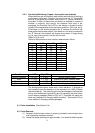
(4) The integrity of the probe can be checked by using an ohmmeter.
Resistance measurement across the insulator of 10 MΩ or greater
indicates the probe is performing satisfactorily. If the system is selected
for detection of high conductivity water (greater than
25 μS), a probe resistance measurement of 1 MΩ or greater may be
considered satisfactory. For the ultra high sensitivity system option (<1μS
conductivity), 20 MΩ is minimum.
(5) After the probes have been inspected, cleaned and tested, they can be
installed following the steps outlined in the probe installation procedure
section.
(6) Do not leave an open probe receptacle on the water column. If for any
reason a probe is not immediately re-installed, the port should be
plugged with Penberthy HP Part No. 964584-19 or Penberthy Part #
10675-022 for LP probes and tightened following the probe installation
procedure.
(7) The unit can now be returned to service by following the steps outlined in
the start-up procedure (see Startup and Operation, section 3).
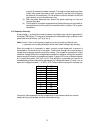
5.3 Electronic Modules and Display(s)
The Model 12B is factory set to detect water with 10μS conductivity. If the
operating water conductivity is significantly different from this value, contact the
factory for replacement sense resistor packages (two per board). The operating
water conductivity will be needed to determine the proper resistor value. When
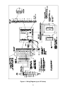
ready to install the new resistor packages, follow these steps (refer to figure 6,
location 6):
(1) Remove power to the unit.
(2) Ensure that proper precautions are taken to prevent electrostatic
discharge to the electronics. Using fingers, remove the old resistor
package by pulling straight out from the socket. A slight rocking motion
can be used if needed. Do not use tools to pry the package out. Do not
use excessive force.
(3) Place the new resistor package into the socket, ensuring all of the pins
are engaged in the socket. Press firmly straight down to seat the resistor
package. Do not use excessive force.
! C A U T I O N !
Any malfunction of the equipment should be attended to immediately. Although any
single channel will fail safe, the overall package is designed for continued
operation. Compounding faults, however, could defeat the internal self-diagnostic
logic, providing misinformation to the operator and possibly subjecting the boiler to
p
otential hazard or nuisance tri
p
s.