


10
3.3.1 Power Supply Fault
Two separate power supplies provide detection power for the Model 12B.
The output of both power supplies are diode shared such that if one
supply fails the remaining supply will carry 100% of the system load.
Each supply has its own full bridge rectifier, filter and a regulator. For the
basic unit, the low voltage transformer with fused input is shared by the
two DC supplies. With the dual transformer option using two independent
power mains, each transformer supplies electrical energy to one DC
power supply. If a fault were to occur within any part of this circuit the
fault circuit would de-energize the electrical fault relay and turn on LED
27 or LED 28 (ref: Fig 6, loc 3) to indicate the fault area and also turn on
the electrical fault LED on the display. If both supplies fail, check the
fuses. Replacement fuses should be rated at 2A 250 V for 120 Vac
mains power or 1A 250 V for optional 240 Vac mains power. One fuse is
used in the “hot” line of 120 Vac supply, one fuse in
each line for 240
Vac supply. The fuses have a polymer guard to prevent personnel
contact, always replace it after changing fuses. There are also two 5
VDC power supplies with diode sharing and thermal and electrical
overload protection. If both 5 VDC power supplies fail the indication is a
loss of all displays and all relays go to the de-energized state.
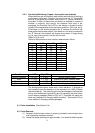
Power supply test points are numbered 1 to 6 (ref: fig 6, loc 4).
TP1 and TP4 should be at +12 VDC.
TP2 and TP5 should be at -12VDC.
TP3 and TP6 should be at +5.75 VDC.
All with a tolerance of ±0.25 VDC.
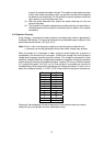
3.3.2 Clock Fault
There are three clock circuits on the Model 12B. Clock 1 operates at 20
Hz and is the steam/water discriminating frequency. If this clock circuitry
fails, the Model 12B will turn on LED 1 (see fig 6, loc 11) and the
electrical fault LED on the display. Loss of this clock is replaced
automatically by a line frequency (50/60Hz) sample (Clock 3). Sensitivity
will be reduced but the unit should still operate if the sensitivity resistor
pack value was properly chosen. Clock 2 at 5KHz is used for open/short
detection. If it fails, LED 2 (see fig 6, loc 11) will turn on as well as the
electrical fault LED on the display. Steam/water detection will still be
operational. Open/short LED’s (see fig 6, loc 9) for all channels will also
turn on with the loss of either primary clock.
! C A U T I O N !
Make sure the mains supply is isolated before replacing the fuse. Working on an
electrically “hot” circuit could cause personal injury and property damage.