


5
the same manner.
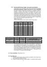
Cascaded Electronic Modules (more than 12 channels) may be installed
with probe wiring in numerical series or interleaved. If interleaving is
used, make certain that the low Electronic Module Probe 1 terminal block
location is wired to the lowest probe or the level fault logic will not work.
The wiring method used must be specified so the level fault logic can be
properly programmed at the factory.
2.6.2 At the Electronic Module
No wiring access holes are drilled in the enclosure. Access holes may be
placed at any convenient point during installation. Use appropriate
fittings, consider EMI and RFI, also maintain the NEMA/IP rating of the
enclosure. The access hole for the probe wiring should contain only
probe wiring. The access hole for the remote display wiring (if used)
should contain only remote display wiring. (Refer to fig 7 through 10 for
display wiring and dimensions).
It is recommended that the relay out and mains power input each have
their own access hole although this is not mandatory. Dress all mains
carrying conductors away from signal wiring.
To ease installation and wiring, the entire module may be removed from
its enclosure by removing the screws holding the metal back plate. Do
not separate the printed circuit board from the back plate.
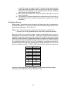
For reliable operation, a mains power source with the following
requirements is required:
120 or 240 Vac
Single Phase, 50/60 Hz
40VA / 80VA, depending on configuration
Mains higher than 240 Vac will require the use of a stepdown
transformer. DC voltages will require use of a voltage inverter.
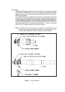
(refer to fig 6, loc 1 and 2)
If a standard unit was specified:
Mains power is connected to TB27 only.
For 120 Vac operation: L1 is “hot”, L2 is “neutral”. A fuse should be
installed at F1. G is for electrical ground.
For 240 Vac operation: L1 and L2 are directly wired. Fuses should be
installed at F1 and F2. G is for electrical ground.
If the dual transformer option was specified:
Mains 1 power is connected as above. Mains 2 power should be sourced
from a different mains supply. Mains 2 power is connected to TB28 only.
Do not run input power through spare conductors in multi-conductor cables
used for probes and display module wiring. Input power is to be run in
separate cable runs.